
Tunable filters for spectral sensing

a filter and spectral sensing technology, applied in the direction of optical radiation measurement, diagnostics using spectroscopy, instruments, etc., can solve the problems of filter size not being sufficiently small to allow, too small tuning range, other disadvantages, etc., and achieve the effect of mitigating one or more of the problems

Active Publication Date: 2017-01-19
KONINKLJIJKE PHILIPS NV
View PDF6 Cites 4 Cited by
  • Summary
  • Abstract
  • Description
  • Claims
  • Application Information

AI Technical Summary

Benefits of technology

The present invention provides a spectroscopic analysis system that addresses the problems of current systems. The invention includes a device with a small light source and a photonic integrated circuit (PIC) with tunable filters. This allows for fast detection and high resolution through the use of filter bank technology. The device is sensitive, portable, and cost-effective, making it suitable for use in mobile or emergency situations. The technical effect of the invention is that it provides a more efficient and accurate method for analyzing samples, with the potential to improve diagnostic devices and expand application areas.

Problems solved by technology

These known filters are either not sufficiently small to allow for the creation of a small spectroscopic analysis device, or suffer from a too small tuning range or have other disadvantages.

Method used


Image

  • Tunable filters for spectral sensing
  • Tunable filters for spectral sensing

Examples


Embodiment Construction

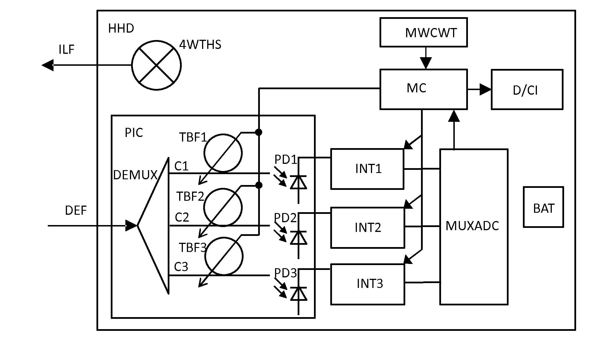
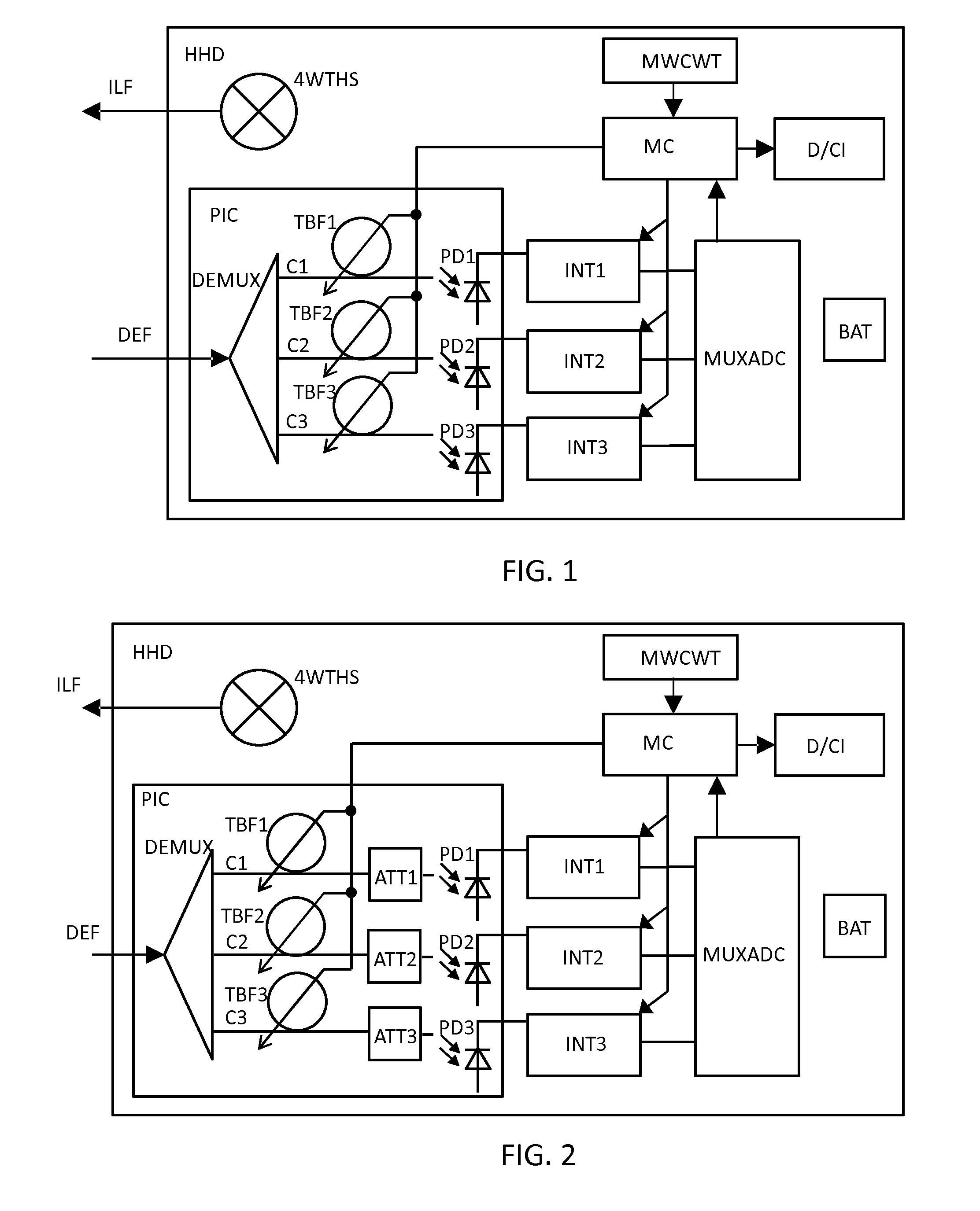
[0014]FIG. 1 shows an embodiment combining a light source (e.g. tungsten halogen exemplified by a 4W Tungsten Halogen light source 4WTHS, LED or laser) with a photonic integrated circuit PIC containing a beam splitter (for example an arrayed waveguide grating (AWG)) and a number of tunable filters (consisting of for example ring cavity resonators), a photo detector per tunable filter output, an electronic integration circuit INT1 . . . INT3 for integrating the photo detector output over time, a multiplexing AD converter MUXADC and a microcontroller MC having a memory MWCWT (Memory with Coefficients and Wavelengths Table) configured to store the relevant wavelength ranges and corresponding spectral coefficients. A battery BAT for powering the device so that it can be used as a handheld device HHD is also illustrated in FIG. 1. To output the data, the device can be equipped with its own display, or controlled via for example a smartphone, smart watch or tablet computer using for examp...


PUM


Abstract

A spectroscopic analysis device for analysis of a sample comprising: a photonic integrated circuit (PIC) comprising: an input (DEF) for receiving light from the sample; and a demultiplexer (DEMUX) arranged to distribute the received light into at least a first optical chain (C1) and a second optical chain (C2); wherein each optical chain (C1, C2) of the photonic integrated circuit C(PIC) further comprises a tunable bandpass filter (TBF1, TBF2) and a variable attenuator (ATT1, ATT2) and a photodetector (PD1, PD2) arranged respectively to filter and to attenuate and to detect the light distributed into its corresponding optical chain (C1, C2).

Description

FIELD OF THE INVENTION[0001]The invention relates to a spectroscopic analysis device for analysis of a sample based on light received from the sample. Furthermore, the invention relates to the spectroscopic analysis and characterization of tissue.BACKGROUND OF THE INVENTION[0002]Devices for spectral tissue sensing and for other spectral sensing methods include a broadband light source and one or more broadband spectrometers. In practice, two of these are included because of the need to cover both the visible and the near infrared wavelength ranges. Example prior art for Spectral Tissue Sensing are disclosed in International Patent Applications WO2012 / 127378, WO2012 / 093309 and WO2013 / 001423. International Patent Application WO2011 / 132128 discloses an example where a limited number of wavelengths are used to detect water and lipid.[0003]This Spectral Tissue Sensing has a great potential in many application areas, especially in the medical applications area. However, to become a succes...

Claims


Application Information

Patent Timeline
IPC IPC(8): G01J3/12G01N21/31G01N21/25G01J3/28
CPCG01J3/12G01J3/28G01N2201/12G01N21/255G01J2003/1213G01N21/31G01N21/474G01N21/49A61B5/7264A61B5/0075A61B5/725G01J3/36G01J2003/1247G01J3/0218G16H50/20G01J3/26
Inventor WIJBRANS, KLAAS CORNELIS JANLUCASSEN, GERHARDUS WILHELMUSHENDRIKS, BERNARDUS HENDRIKUS WILHELMUS
Owner KONINKLJIJKE PHILIPS NV
Learn More