Isothermal tubular catalytic reactor

a catalytic reactor and tubular technology, applied in the field of isothermal tubular catalytic reactors, can solve the problems of laborious filling and emptying operations, rapid deterioration of catalysts, and non-uniform flow amongst, and achieve the effects of facilitating filling and emptying of catalysts, and reducing the number of clogging

Inactive Publication Date: 2017-02-02
CASALE SA
View PDF3 Cites 4 Cited by
  • Summary
  • Abstract
  • Description
  • Claims
  • Application Information

AI Technical Summary

Benefits of technology

[0026]The tubes are advantageously arranged with a triangular or square pitch. The arrangement of the tubes with a triangular pitch may be preferred since it allows a greater density of heat exchange area in relation to the catalyst volume.
[0027]The rods supporting the tubes with a larger pitch have the advantage of leaving more free space and facilitating filling and emptying of the catalyst, as well as settling of the catalyst at the initial start-up. In fact, compared to the known rod-baffle systems, the tubes are less constrained, but there is the significant advantage of having a bundle structure which is much more open for the operations involving filling / emptying of the catalyst and for settling thereof.

Problems solved by technology

However, they also have several drawbacks: the quantity of catalyst they may contain is relatively small, being limited by the volume inside the tubes; they have high pressure losses in the tube side; they suffer from the different expansion of the tubes and the catalyst during the heat cycles (for example in the transients); the difference in expansion and the high pressure losses may cause a rapid deterioration of the catalyst; the catalyst filling and emptying operations are laborious; any lack of uniformity during filling of the catalyst produces a non-uniform flow among the various tubes with negative consequences for the reactor performances.
Another drawback of these reactors consists in the cost of the tube plates, especially if, as usually occurs, one or both the sides (tube side and / or shell side) are subject to a significant pressure.
However, they are also not satisfactory.
Shell-side catalyst reactors equipped with a conventional tube plate have the disadvantage of being difficult to access for filling and emptying of the catalyst.
In an attempt to solve this problem, reactors have been proposed where the tube plate is replaced by headers with a complex design (for example in the form of an involute of a circle), which improve within certain limits the accessibility to the catalyst, but cannot withstand high differences in pressure between the shell side and the tube side.
Another drawback of these reactors is that they operate with an axial flow and, for this reason, they have pressure losses in the shell side, via the catalyst, which are in any case high.
However, it also has a number of drawbacks: it requires a complicated system of headers for supplying the tubes and collecting the outgoing fluid and has a conversion efficiency which is not entirely satisfactory.

Method used


Image

  • Isothermal tubular catalytic reactor
  • Isothermal tubular catalytic reactor
  • Isothermal tubular catalytic reactor

Examples


Embodiment Construction

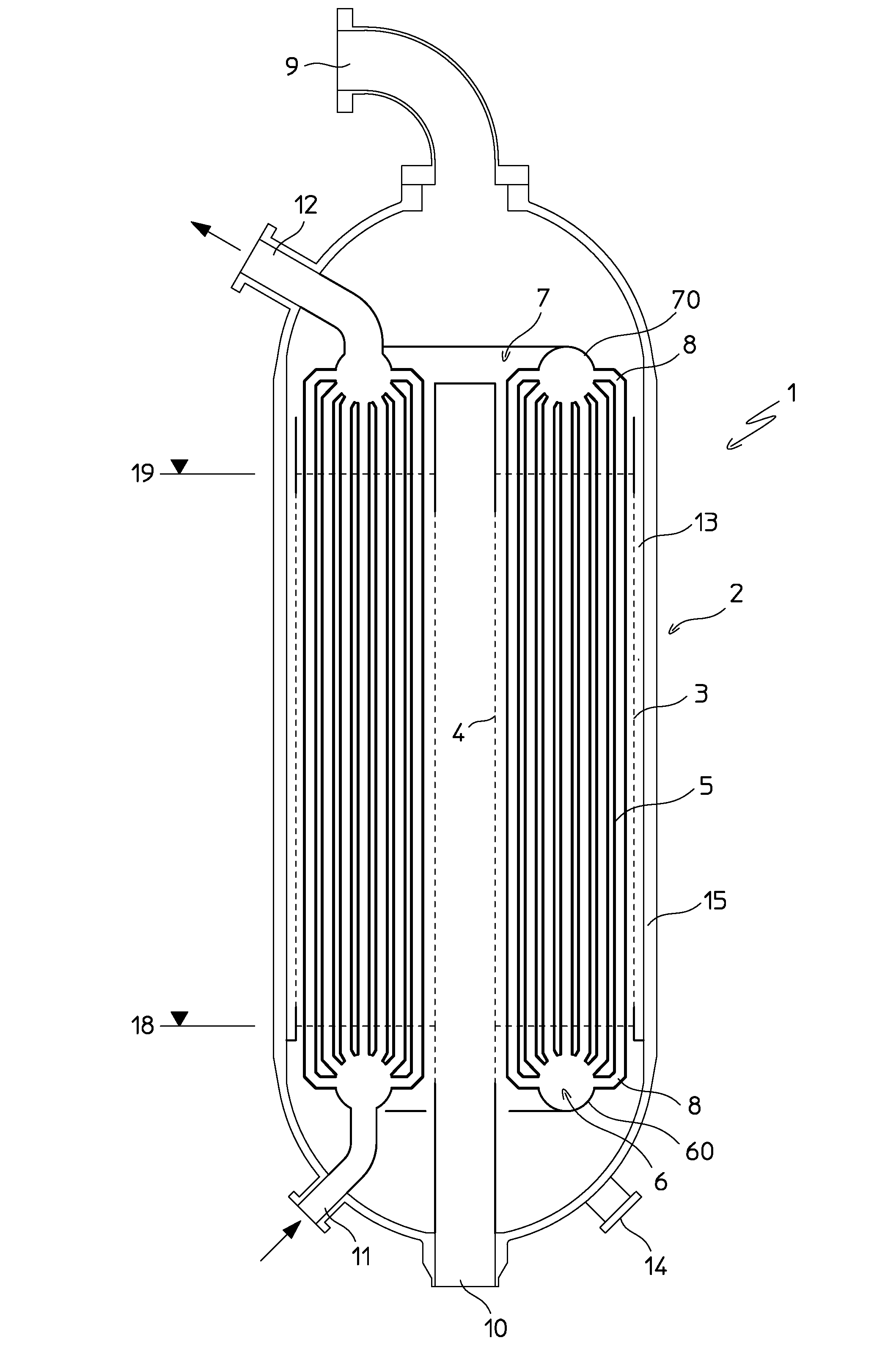
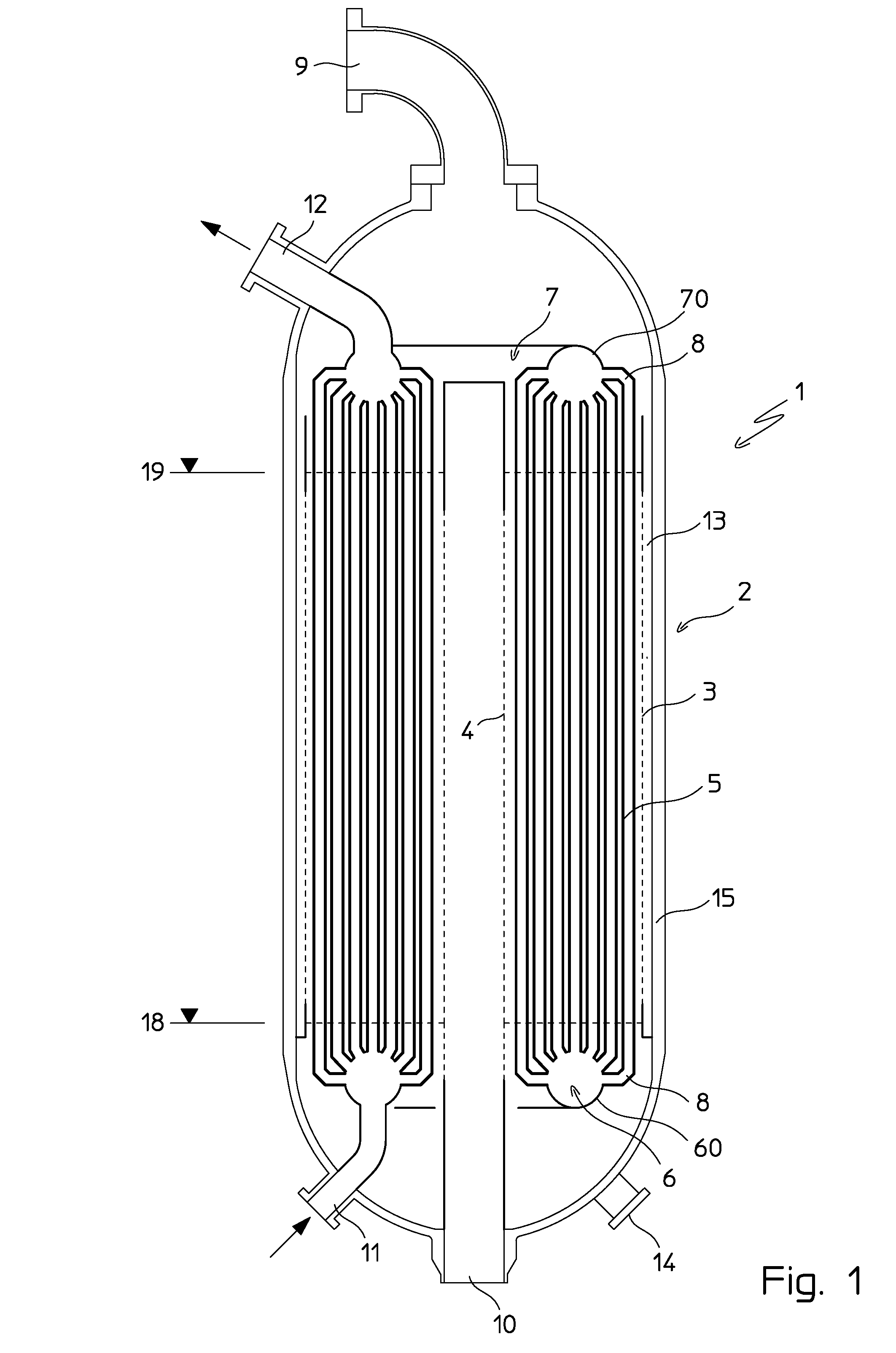
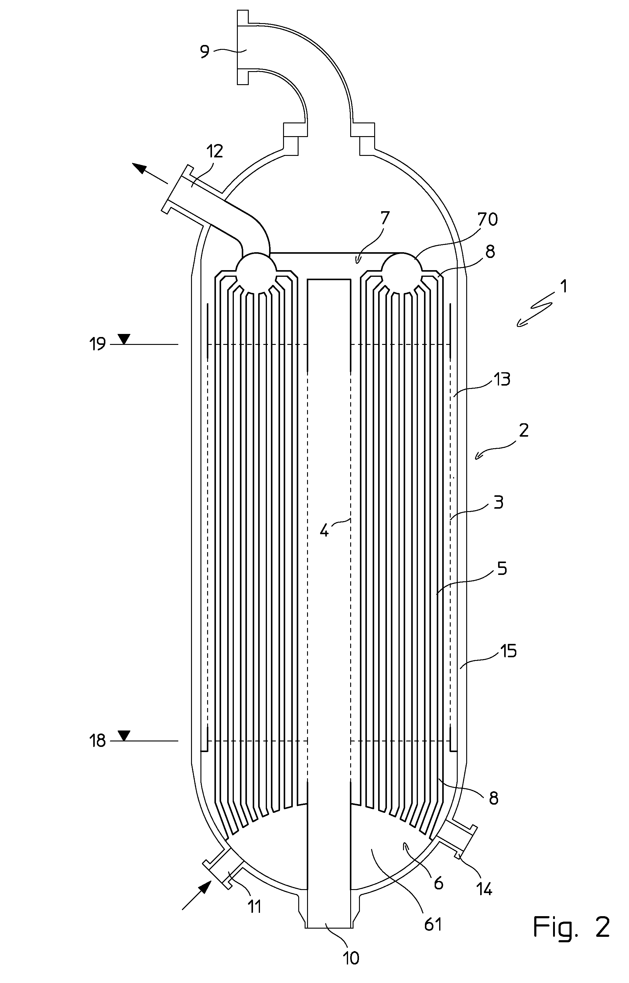
[0039]FIG. 1 shows a vertical reactor 1 comprising a catalytic bed 2 and a tubular heat exchanger immersed in said catalytic bed.

[0040]The catalytic bed 2 is contained in a substantially annular space between a cylindrical wall 3 and a central tube 4 coaxial with said wall 3. Both the cylindrical wall 3 and the central tube 4 have at least part of the surface perforated so as to allow the passage of the reagents and gaseous products. The catalytic bed is supported by a basket (not shown) according to the art known per se. The lines 18 and 19 indicate the volume filled with catalyst during conditions of normal use; below the line 18 there is usually inert material.

[0041]The tubular heat exchanger comprises essentially a straight tube bundle 5. The tubes 5 are housed inside the annular space between the wall 3 and the central tube 4.

[0042]The ends of the tubes are connected to two bodies 6 and 7 which act as a distributor and a header for a heat exchange fluid. Each tube 5 is connecte...


PUM

PropertyMeasurementUnit
lengthaaaaaaaaaa
circumferencesaaaaaaaaaa
shapeaaaaaaaaaa

Abstract

Isothermal catalytic reactor (1) comprising a catalytic bed (2) and a tubular heat exchanger immersed in said catalytic bed, wherein the exchanger is formed by straight tubes connected to a distributor (6) and to a header (7) formed by preferably toroidal bodies which support the said tubes, and wherein the catalytic bed is of the type crossed by an inward radial flow.

Description

FIELD OF APPLICATION[0001]The invention relates to an isothermal catalytic reactor containing a tubular heat exchanger.PRIOR ART[0002]An isothermal catalytic reactor is defined as a reactor containing a catalytic bed and a heat exchanger immersed in the bed and designed to supply heat or remove heat in order to maintain the temperature of the catalyst within a predefined range.[0003]The invention relates in particular to reactors of the aforementioned type in which the heat exchanger is a tubular exchanger. Said reactors, for the sake of brevity, are also called isothermal tubular reactors.[0004]Isothermal tubular catalytic reactors may be distinguished depending on positioning of the catalyst which may be in the tube side, i.e. inside the tubes, or in the shell side, i.e. around said tubes.[0005]Reactors with tubes filled with catalyst are constructionally simple and offer the advantage that they have a large exchange area in relation to the quantity of catalyst. However, they also...

Claims


Application Information

Patent Timeline
Patent Type & Authority Applications(United States)
IPC IPC(8): B01J8/02C07C29/00B01J19/00B01J19/24C01B3/16C01C1/04
CPCB01J8/0285B01J8/0221C01B3/16C01C1/0441B01J19/006B01J2219/00763C07C29/00B01J2208/00132C01B2203/0283C01B2203/08B01J19/2415
Inventor FILIPPI, ERMANNORIZZI, ENRICOREDAELLI, LUCADEODATO, GUGLIELMO
Owner CASALE SA
Why Eureka
Try Eureka