

Transducer including fibers and outputting and inputting an electric signal
- Summary
- Abstract
- Description
- Claims
- Application Information
AI Technical Summary
Benefits of technology
Problems solved by technology
Method used
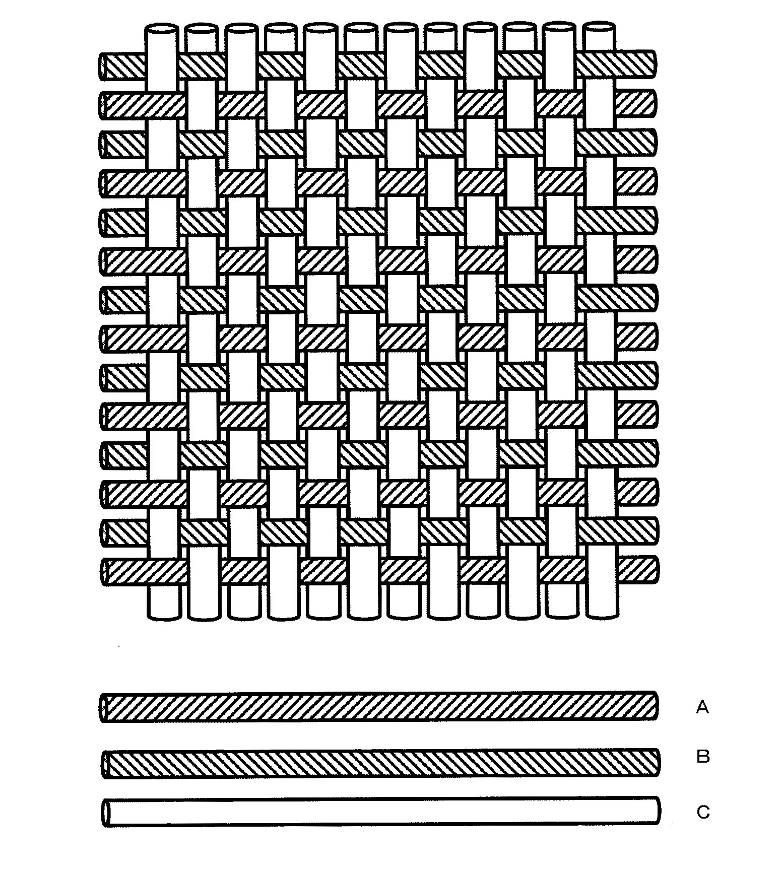
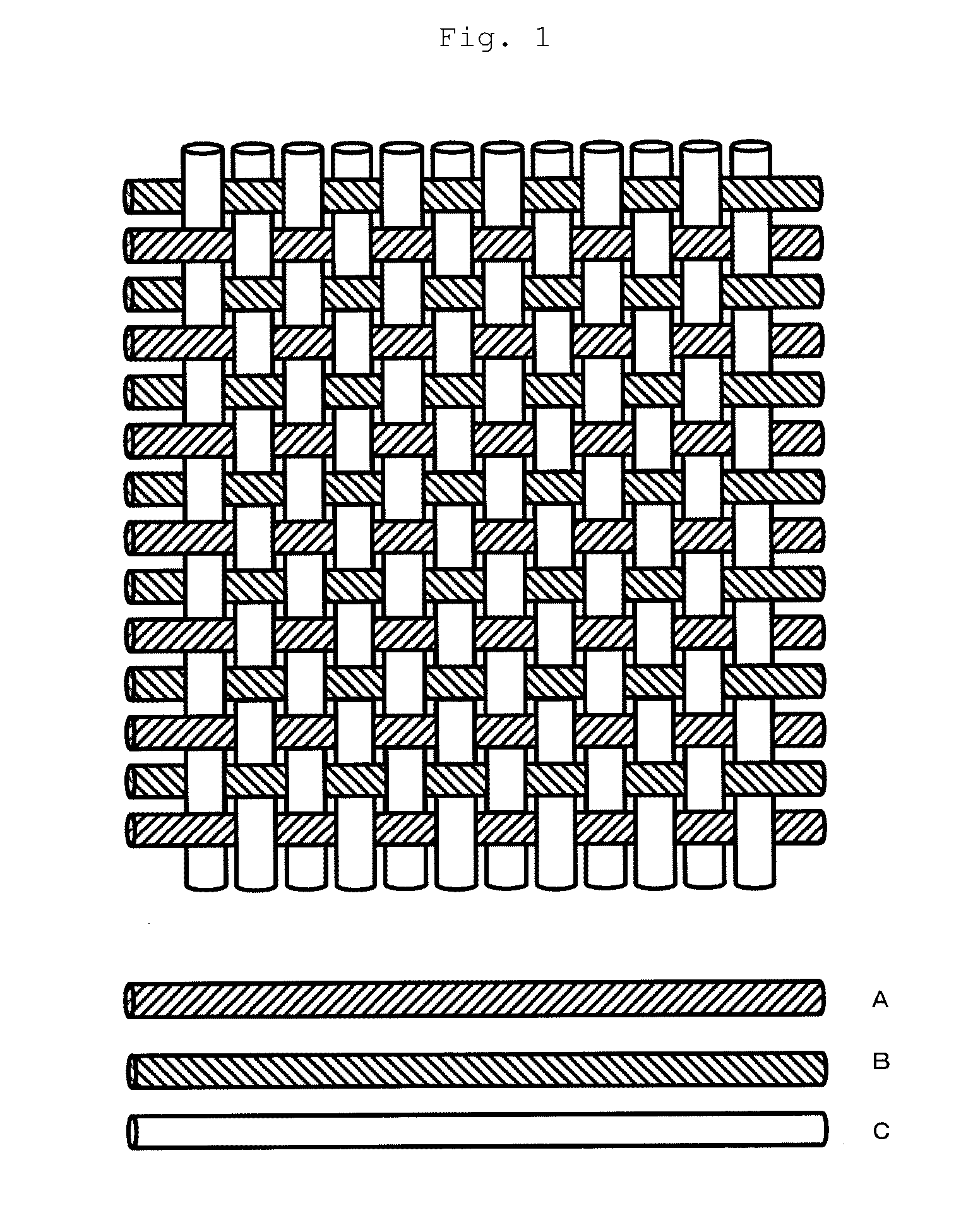
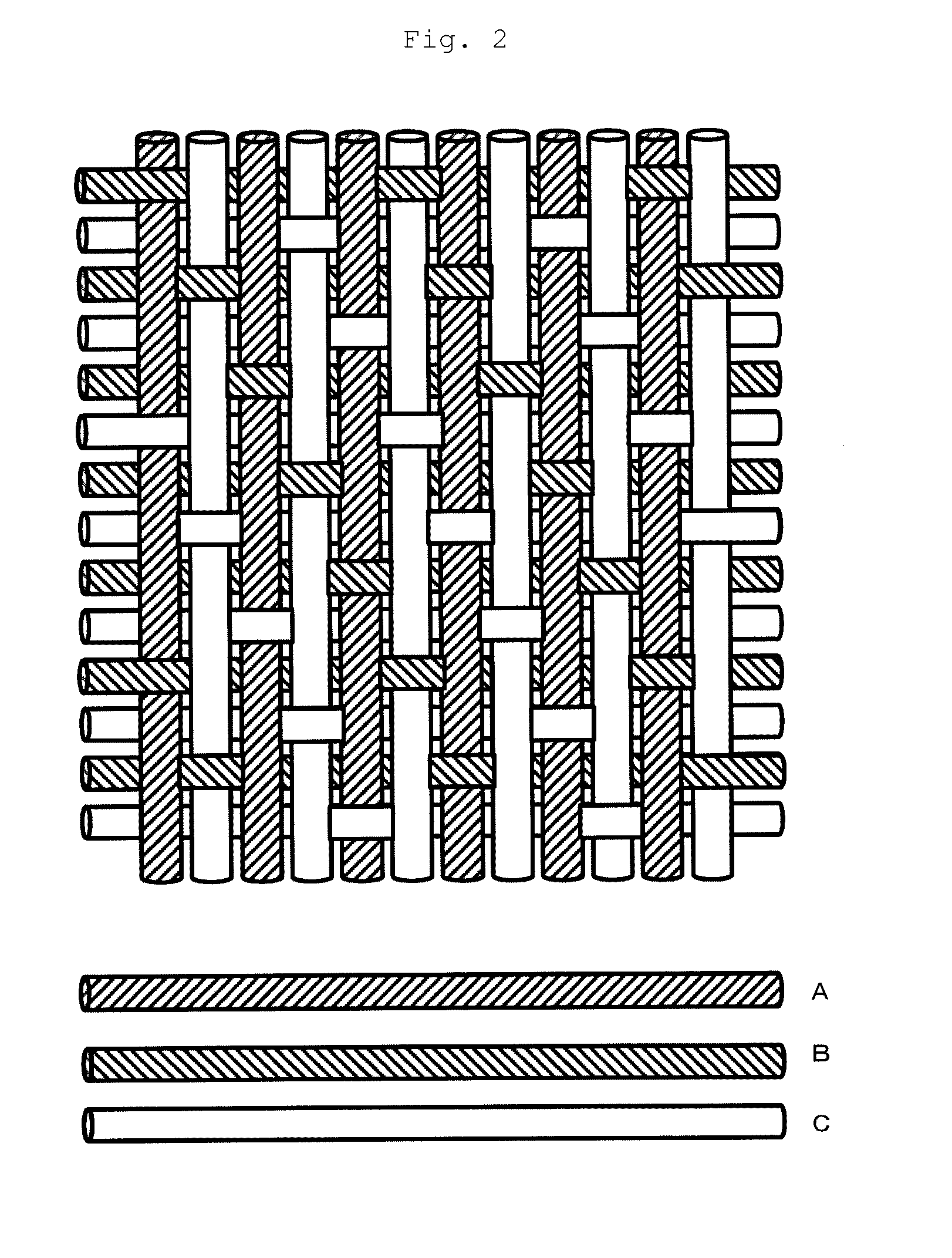
Image

Examples
embodiment 1
(Another Embodiment 1 of Piezoelectric Element)
[0111]The present invention includes a transducer including the following piezoelectric element of another embodiment. (FIG. 13, Embodiment 8).[0112]1. A piezoelectric element including a conductive fiber obtained by coating a fiber with an electric conductor, a piezoelectric polymer covering the surface of the conductive fiber and a surface conductive layer formed on the surface of the piezoelectric polymer.[0113]2. The piezoelectric element in the above paragraph 1, wherein the piezoelectric polymer comprises polylactic acid as the main component.[0114]3. The piezoelectric element in the above paragraph 1 or 2, wherein the piezoelectric polymer comprises poly-L-lactic acid or poly-D-lactic acid as the main component, and the optical purities of these are not less than 99%.[0115]4. The piezoelectric element in the above paragraph 2 or 3, wherein the piezoelectric polymer is uniaxially oriented and contains a crystal.[0116]5. The piezoe...
example 1
(Production of Polylactic Acid)
[0204]The polylactic acid used in Example 1 was manufactured by the following method.
[0205]0.005 part by weight of tin octylate was added to 100 parts by weight of L-lactide (manufactured by Musashino Chemical Laboratory, Ltd., optical purity of 100%) to carry out a reaction in a nitrogen atmosphere at 180° C. for 2 hours in a reactor equipped with a stirring blade, phosphoric acid was added in an amount which was 1.2 times the equivalent of tin octylate, the residual lactide was removed under a reduced pressure of 13.3 Pa, and the resulting product was formed into a chip to obtain poly-L-lactic acid (PLLA1). The obtained PLLA1 had a weight average molecular weight of 152,000, a glass transition point (Tg) of 55° C. and a melting point of 175° C.
(Piezoelectric Fiber)
[0206]PLLA1 molten at 240° C. was discharged from a cap having 24 holes at a rate of 20 g / min and taken up at a rate of 887 m / min. This undrawn multifilament yarn was drawn to 2.3 times at ...
example 2
(Production of Polylactic Acid)
[0212]The polylactic acid used in Example 2 was manufactured by the following method.
[0213]0.005 part by weight of tin octylate was added to 100 parts by weight of L-lactide (manufactured by Musashino Chemical Laboratory, Ltd., optical purity of 100%) to carry out a reaction in a nitrogen atmosphere at 180° C. for 2 hours in a reactor equipped with a stirring blade, phosphoric acid was added in an amount which was 1.2 times the equivalent of tin octylate, the residual lactide was removed under a reduced pressure of 13.3 Pa, and the resulting product was formed into a chip to obtain poly-L-lactic acid (PLLA1). The obtained PLLA1 had a weight average molecular weight of 152,000, a glass transition point (Tg) of 55° C. and a melting point of 175° C.
(Piezoelectric Fiber)
[0214]PLLA1 molten at 240° C. was discharged from a cap having 24 holes at a rate of 20 g / min and taken up at a rate of 887 m / min. This undrawn multifilament yarn was drawn to 2.3 times at ...
PUM
| Property | Measurement | Unit |
|---|---|---|
| Fraction | aaaaa | aaaaa |
| Fraction | aaaaa | aaaaa |
| Flexibility | aaaaa | aaaaa |
Abstract
Description
Claims
Application Information