
Reconfigurable Microwave Filters

a microwave filter and reconfigurable technology, applied in the field of filters, can solve the problems of degraded efficacy of electronic countermeasure systems used by armed forces, and the frequent interference of naval vessels by co-site sites

Active Publication Date: 2017-02-09
INDIANA MICROELECTRONICS
View PDF2 Cites 5 Cited by
  • Summary
  • Abstract
  • Description
  • Claims
  • Application Information

AI Technical Summary

Benefits of technology

The patent describes a reconfigurable microwave filter that can adjust the resonant frequency of its cavity resonators based on a control circuit. Each control circuit is capacitively coupled to a corresponding cavity resonator and can control it by varying the capacitance of a center post or an inductance of a feedback circuit. The feedback circuit senses the capacitance of the control circuit and generates a feedback signal that is indicative of the resonant frequency of the cavity resonator. The control circuit adjusts the resonant frequency of the cavity resonator based on the feedback signal. The reconfigurable microwave filter can be used in electronic systems to filter out unwanted signals or to adjust the resonant frequency of a cavity resonator for different applications.

Problems solved by technology

Electronic systems used by armed forces (e.g., voice communications, data communications, satellite communications, telemetry, navigation, radar, electronic warfare, and / or electronic counter measure systems) may suffer from degraded efficacy resulting, for example, from co-site interference and / or jamming.
Co-site interference is due to multiple electronic systems, typically located at or near the same physical location (e.g., co-located), electrically interfering with one another.
For example, naval vessels often suffer from co-site interference because of numerous antennas and other electronic systems being located on or around the vessel's mast.
Hostile jamming occurs when an entity intentionally broadcasts radio frequency (RF) signals with the intent of disrupting or disabling electronic systems (e.g., land- or vessel-based electronic systems of adversarial armed forces).
Unintentional jamming occurs when an entity broadcasts RF signals that have the unintentional consequence of disrupting or disabling electronics systems.

Method used


Image

  • Reconfigurable Microwave Filters
  • Reconfigurable Microwave Filters
  • Reconfigurable Microwave Filters

Examples


Embodiment Construction

[0037]While the concepts of the present disclosure are susceptible to various modifications and alternative forms, specific exemplary embodiments thereof have been shown by way of example in the figures and will herein be described in detail. It should be understood, however, that there is no intent to limit the concepts of the present disclosure to the particular forms disclosed, but on the contrary, the intention is to cover all modifications, equivalents, and alternatives falling within the spirit and scope of the present disclosure.

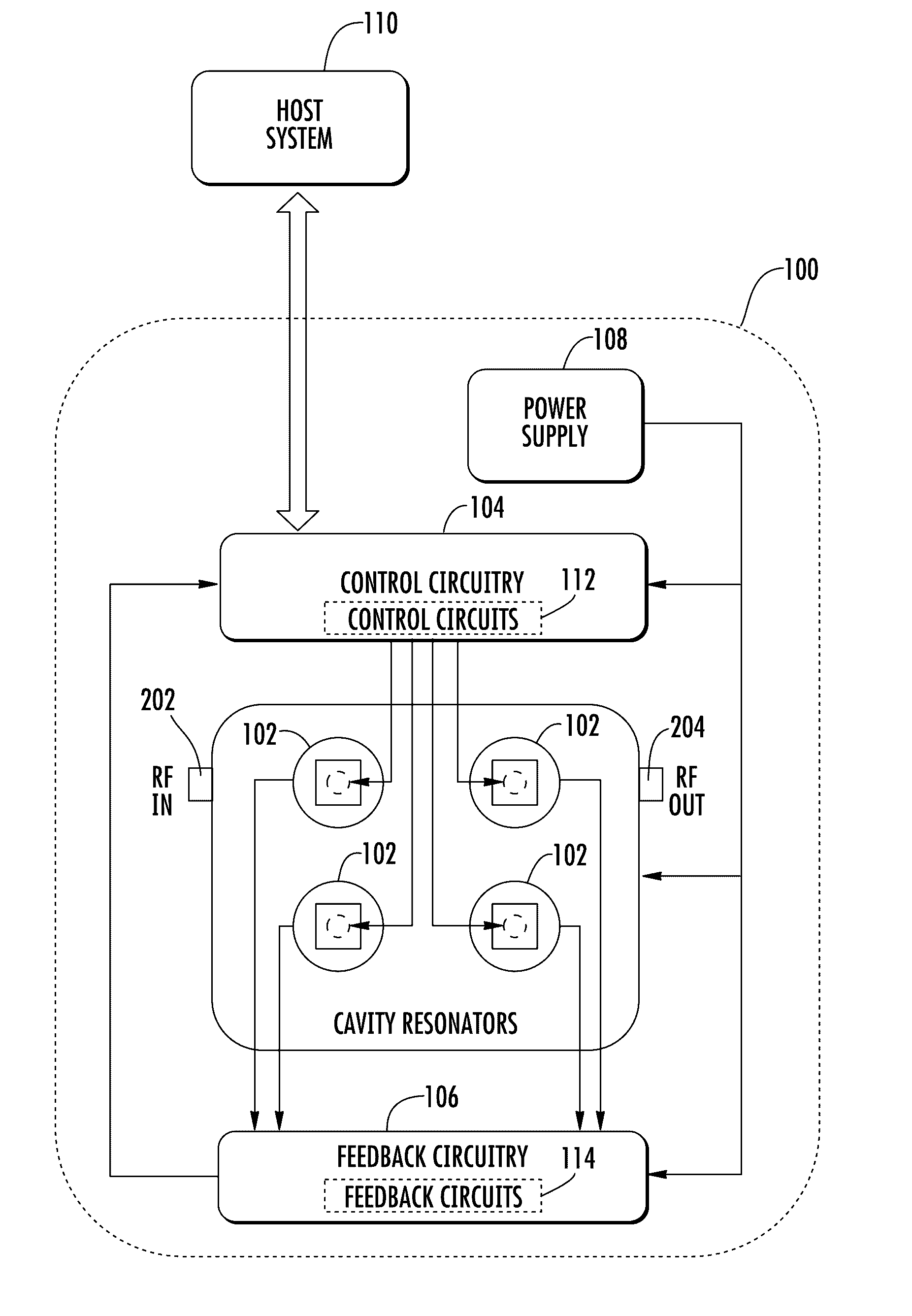
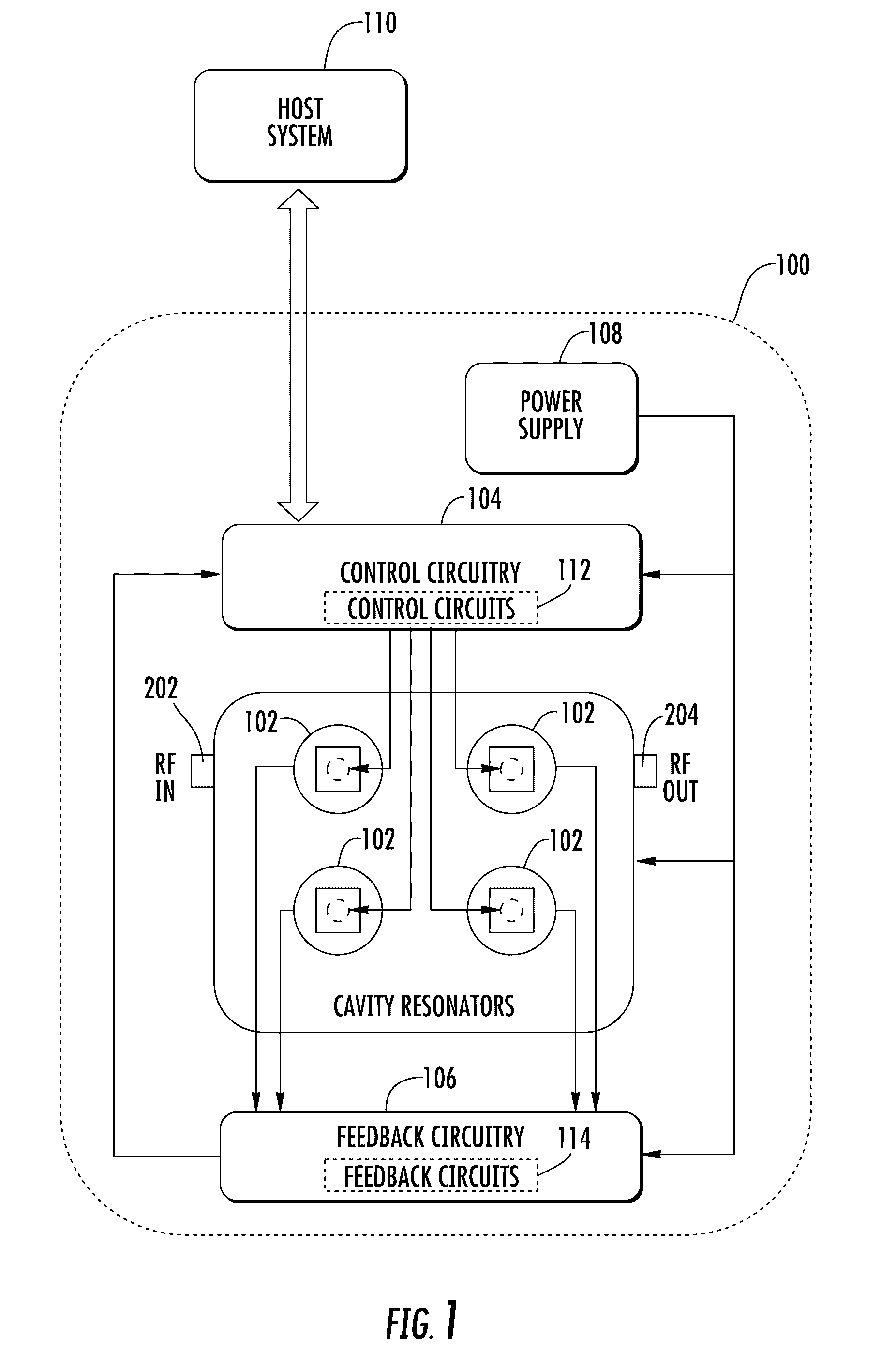
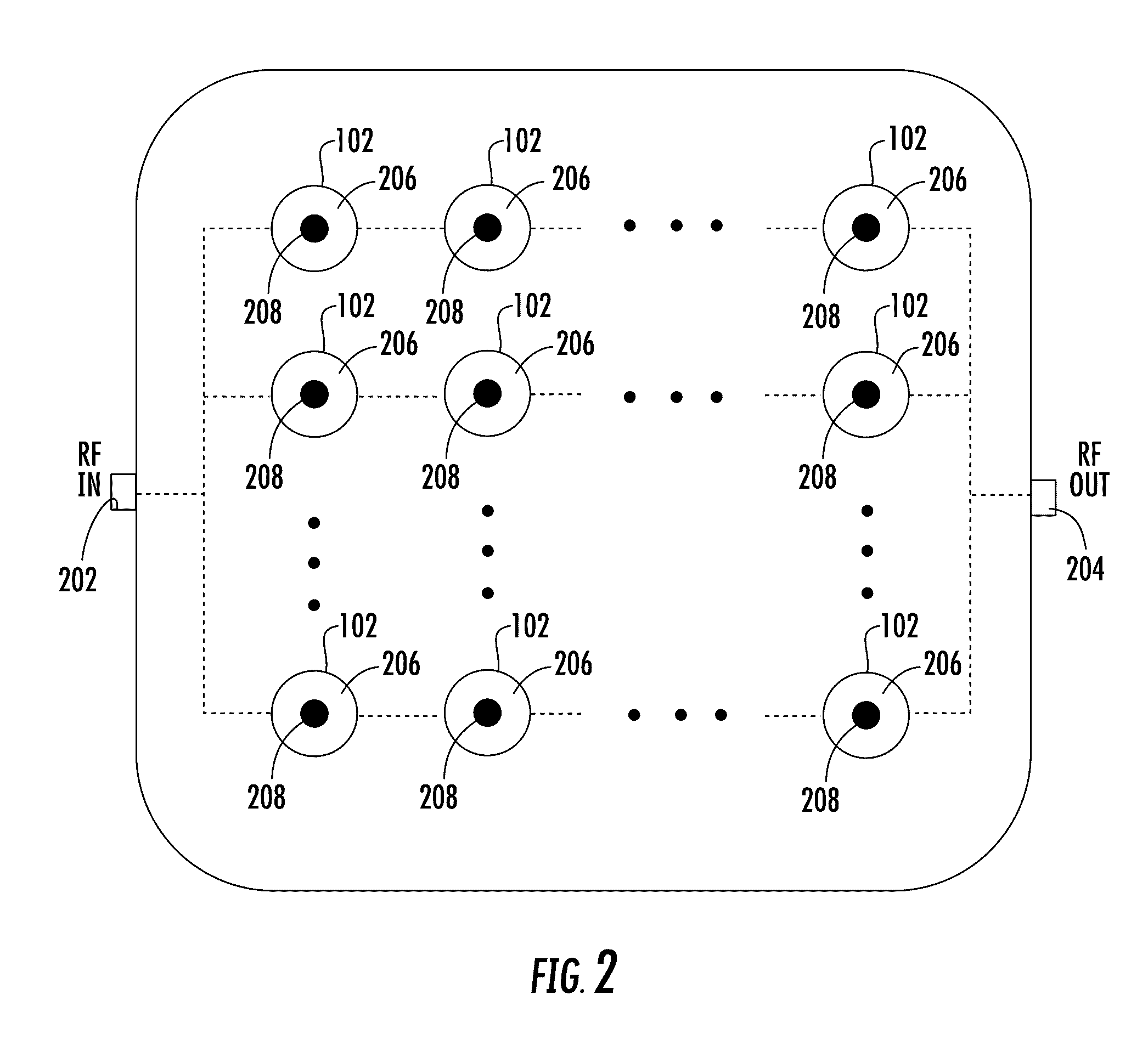
[0038]Referring now to FIG. 1, a reconfigurable microwave filter 100 includes a plurality of cavity resonators 102, control circuitry 104, feedback circuitry 106, and a power supply 108. Additionally, as shown, the illustrative reconfigurable microwave filter 100 may be communicatively coupled to a host system 110. As described in detail below, various parameters of the reconfigurable microwave filter 100 may be dynamically configurable, depending on ...


PUM


Abstract

Illustrative embodiments of reconfigurable microwave filters, as well as associated systems and methods, are disclosed. In at least one illustrative embodiment, a reconfigurable microwave filter may comprise a plurality of cavity resonators on a common substrate and a plurality of control circuits each configured to control a resonant frequency of one of the plurality of cavity resonators. The reconfigurable microwave filter may also comprise a plurality of feedback circuits each configured to generate a feedback signal that is indicative of the resonant frequency of one of the plurality of cavity resonators and to transmit the feedback signal to one of the plurality of control circuits.

Description

CROSS-REFERENCE TO RELATED APPLICATION[0001]This application claims the benefit of U.S. Provisional Patent Application No. 61 / 984,408, filed Apr. 25, 2014 (entitled “Reconfigurable Microwave Filter with Automatic Feedback and Control for Stabilized Programmable Center Frequency and Bandwidth”), the entire disclosure of which is incorporated by reference herein.STATEMENT REGARDING FEDERALLY SPONSORED RESEARCH[0002]This invention was made with government support under Contract Nos. W31P4Q-13-C-016 and W31P4Q-12-C-0210 awarded by DARPA and Contract Nos. N00164-13-C-GR38 and N00014-11-M-0305 awarded by the United States Navy. The government has certain rights in the invention.TECHNICAL FIELD[0003]The present disclosure relates, generally, to filters and, more particularly, to reconfigurable microwave filters (RMFs).BACKGROUND[0004]Electronic systems used by armed forces (e.g., voice communications, data communications, satellite communications, telemetry, navigation, radar, electronic w...

Claims


Application Information

Patent Timeline
Patent Type & Authority Applications(United States)
IPC IPC(8): H04B3/04H03H7/01H03J1/06H01P1/208
CPCH03J1/06H03H7/0123H01P1/208H01P1/2053H01P7/04H03H7/0153H03H7/004
Inventor HOPPENJANS, ERIC E.CUPPY, STEVEN J.
Owner INDIANA MICROELECTRONICS
Learn More