Ultrasound imaging pickup apparatus

a pickup apparatus and ultrasonic technology, applied in ultrasonic/sonic/infrasonic image/data processing, instruments, applications, etc., can solve the problems of difficult to improve the resolution in the direction of an azimuthal angle, and the inability to prepare an array of infinite length

Active Publication Date: 2017-02-16
HITACHI LTD
View PDF0 Cites 6 Cited by
  • Summary
  • Abstract
  • Description
  • Claims
  • Application Information

AI Technical Summary

Benefits of technology

[0010]As shown in Patent Literature 1, delay times are calculated in the irradiation area of a transmission beam (in an area where ultrasound energy is converged) using the virtual source method, and delay times are calculated under the assumption that a spherical wave is irradiated from the end of a probe outside of the irradiation area of the transmission beam (in areas where the energy of the ultrasound beam disperses), which makes it possible to obtain phased signals even at points outside of the irradiation area of the transmission beam. Therefore, reception scanning lines can be set even outside of the irradiation area of the transmission beam.
[0011]However, in the case where delay times at points on a reception scanning line outside of the irradiation area of the transmission beam are calculated using the waveform of a spherical wave which is considered to be irradiated from the end of the probe according to the technology disclosed in Patent Literature 1, the waveform of the spherical wave used for calculation of the delay times have to be switched from the waveform of a spherical wave irradiated from the left part of the edge of the probe to the waveform of a spherical wave irradiated from the right part of the edge of the probe or vice versa in the vicinity of the depth of a transmit focus. Owing to this switching, there arises a problem in that a curve representing the variation between delay times in the direction of the depth along the reception scanning line becomes discontinuous in the vicinity of the depth of the transmit focus. The discontinuity of the variation between the delay times in the vicinity of the depth of the transmit focus incurs the discontinuity of the pixel values of a generated ultrasound image in the vicinity of the depth of the transmit focus, so that an artifact is generated in the vicinity of the depth of the transmit focus.
[0012]One of the objects of the present invention is to execute reception beamforming that does not generate discontinuity in the vicinity of the depth of the transmit focus even if reception scanning lines are disposed outside of the irradiation area of a focusing-type transmission beam.

Problems solved by technology

Because the transmission / reception of ultrasound waves by an ultrasound image pickup apparatus is performed by means of an array with an aperture of a finite diameter, the transmission or reception is affected by the diffractions of the ultrasound waves caused by the edge of the aperture, therefore it is difficult to improve the resolution in the direction of an azimuthal angle.
The above problem can be solved if an array of an infinite length can be prepared, but in actuality it is impossible to prepare an array of an infinite length.

Method used


Image

  • Ultrasound imaging pickup apparatus
  • Ultrasound imaging pickup apparatus
  • Ultrasound imaging pickup apparatus

Examples


first embodiment

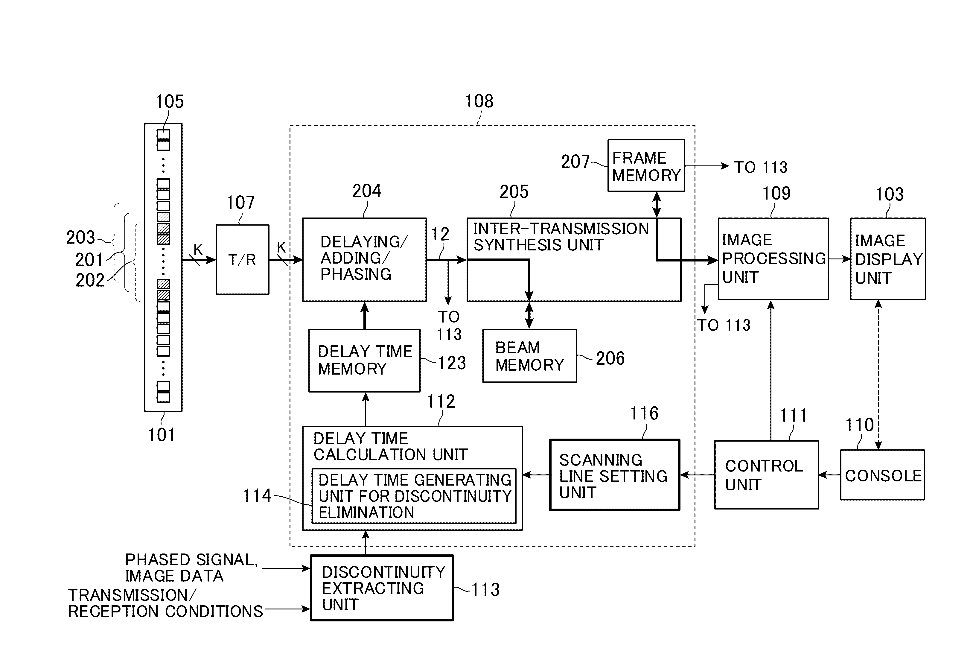
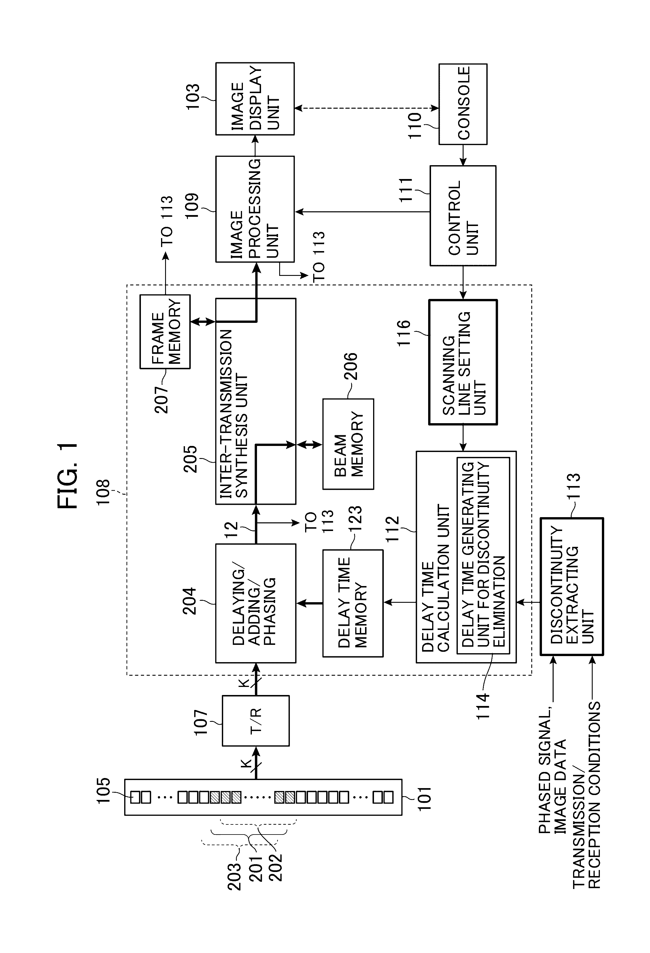
[0033]An ultrasound image pickup apparatus of a first embodiment will be explained with reference to FIG. 1.

[0034]The ultrasound image pickup apparatus of the first embodiment includes: a reception beamformer 108 that delays reception signals, which are received by plural ultrasound elements 105, by delay times at respective predefined points on reception scanning lines, phases the delayed reception signals, and then adds these signals to get phased signals 12; a discontinuity extracting unit 113; and a delay time generating unit 114 for discontinuity elimination. The discontinuity extracting unit 113 detects the degree of discontinuity showing the discontinuity of the wave fronts of the phased signals 12. If there is an area where the degree of discontinuity is larger than a predefined value, the delay time generating unit 114 for discontinuity elimination changes delay times in the area where the discontinuity is generated.

[0035]As mentioned above, in the first embodiment, whether...

second embodiment

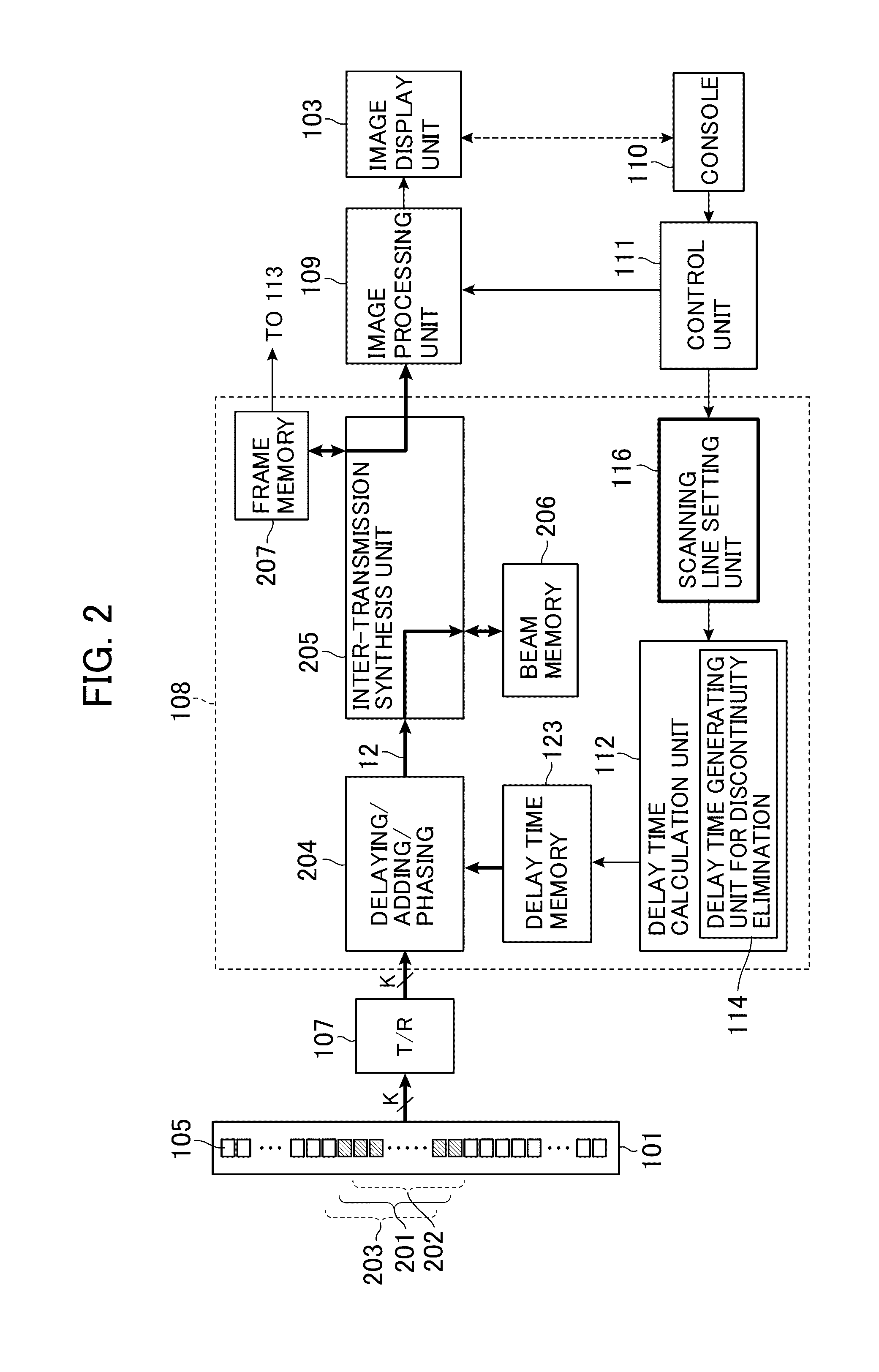
[0038]An ultrasound image pickup apparatus of a second embodiment will be explained with reference to FIG. 2, FIGS. 3(a) and (b). FIG. 2 is a block diagram showing a part of the apparatus, FIG. 3(a) is a perspective view of the apparatus, and FIG. 3(b) is a block diagram showing the schematic configuration of the entirety of the apparatus.

[0039]As shown in FIG. 2, FIGS. 3(a) and (b), the ultrasound image pickup apparatus of the second embodiment includes: an ultrasound element array 101 in which plural ultrasound elements 105 are arranged in a predefined direction; a transmission beamformer 104 that makes at least apart (201, 202, and 203) of the plural ultrasound elements 105 transmit a focusing-type transmission beam to the imaged area of a test object 100; a reception beamformer 108 that delays reception signals output by the plural of ultrasound elements 105, which receive ultrasound waves from the test object 100, by delay times to phase the reception signals, and outputs phase...

third embodiment

[0083]In a third embodiment, the delay time generating unit 114 for discontinuity elimination generates the curve 92 (refer to points A in FIG. 6) that continuously connects the curve 72 of delay times caused by a forward diffracted wave and the curve 73 of delay times caused by a backward diffracted wave using below Expressions (9-1), (9-2), (10-1), and (10-2).

[0084]As is clear from FIG. 6, the curve 92 is a two-step curve that has a part (B1) connecting the curve 72 showing the variation between delay times in the shallow area B1 and a straight line 75 showing the variation between delay times determined on the basis of plane wave propagation, and a part (B2) connecting the straight line 75 based on the plane wave propagation and the curve 73 showing the variation between delay times in the deep area B2.

[0085]Both Expressions (9-1) and (9-2) are expressions used for determining weighting functions using a sigmoid function as is the case of Expression (3). In this embodiment, an ar...


PUM


Abstract

Reception beamforming that does not generate discontinuity in the vicinity of the depth of a transmit focus is executed even if reception scanning lines are disposed outside of the irradiation area of a focusing-type transmission beam. The degree of discontinuity showing the discontinuity of reception signals detected by plural ultrasound elements 105 or the degree of discontinuity regarding the discontinuity of the wave fronts of phased signals is detected by a discontinuity extracting unit 113. If there is an area where the degree of discontinuity is larger than a predefined value, a delay time generating unit 114 for discontinuity elimination changes the delay times in the area where the discontinuity is generated.

Description

TECHNICAL FIELD[0001]The present invention relates to an ultrasound imaging technology that takes images inside of a test object using ultrasound waves.BACKGROUND ART[0002]The ultrasound imaging technology is a technology that takes images of the inside of a test object such as a human body noninvasively using ultrasound waves (inaudible sound waves, that is, sound waves whose frequencies are typically 20 kHz or higher).[0003]As a transmission method for transmitting an ultrasound beam from an ultrasound probe to a test object such as a human body, there are two kinds of transmission methods, and one is a dispersing-type transmission method in which an ultrasound beam that disperses in a fan shape is transmitted, and another is a focusing-type transmission method in which the transmit focus of an ultrasound beam is disposed inside of a test object, and the ultrasound beam is converged on the focus.[0004]Because the transmission / reception of ultrasound waves by an ultrasound image pi...

Claims


Application Information

Patent Timeline
Patent Type & Authority Applications(United States)
IPC IPC(8): A61B8/00A61B8/08A61B8/14
CPCA61B8/4488A61B8/5269A61B8/14A61B8/145A61B8/5207G01S7/5205G01S7/52085G01S15/8915G01S15/8997G10K11/346A61B8/00G01N29/262
Inventor IKEDA, TEIICHIROMASUZAWA, HIROSHITAKANO, SHINTAISHIHARA, CHIZUESUZUKI, MAYUMI
Owner HITACHI LTD
Why Eureka
Try Eureka