Monitoring sensor for sealed secondary battery, sealed secondary battery, and monitoring method for sealed secondary battery

a secondary battery and monitoring sensor technology, applied in the direction of batteries, sustainable manufacturing/processing, instruments, etc., can solve the problems of secondary battery rupture, detection is not carried out, and the sealing structure is hindered, so as to achieve the effect of high sensitivity and no obstruction of the sealing structur

Inactive Publication Date: 2017-02-16
TOYO TIRE & RUBBER CO LTD
View PDF12 Cites 6 Cited by
  • Summary
  • Abstract
  • Description
  • Claims
  • Application Information

AI Technical Summary

Benefits of technology

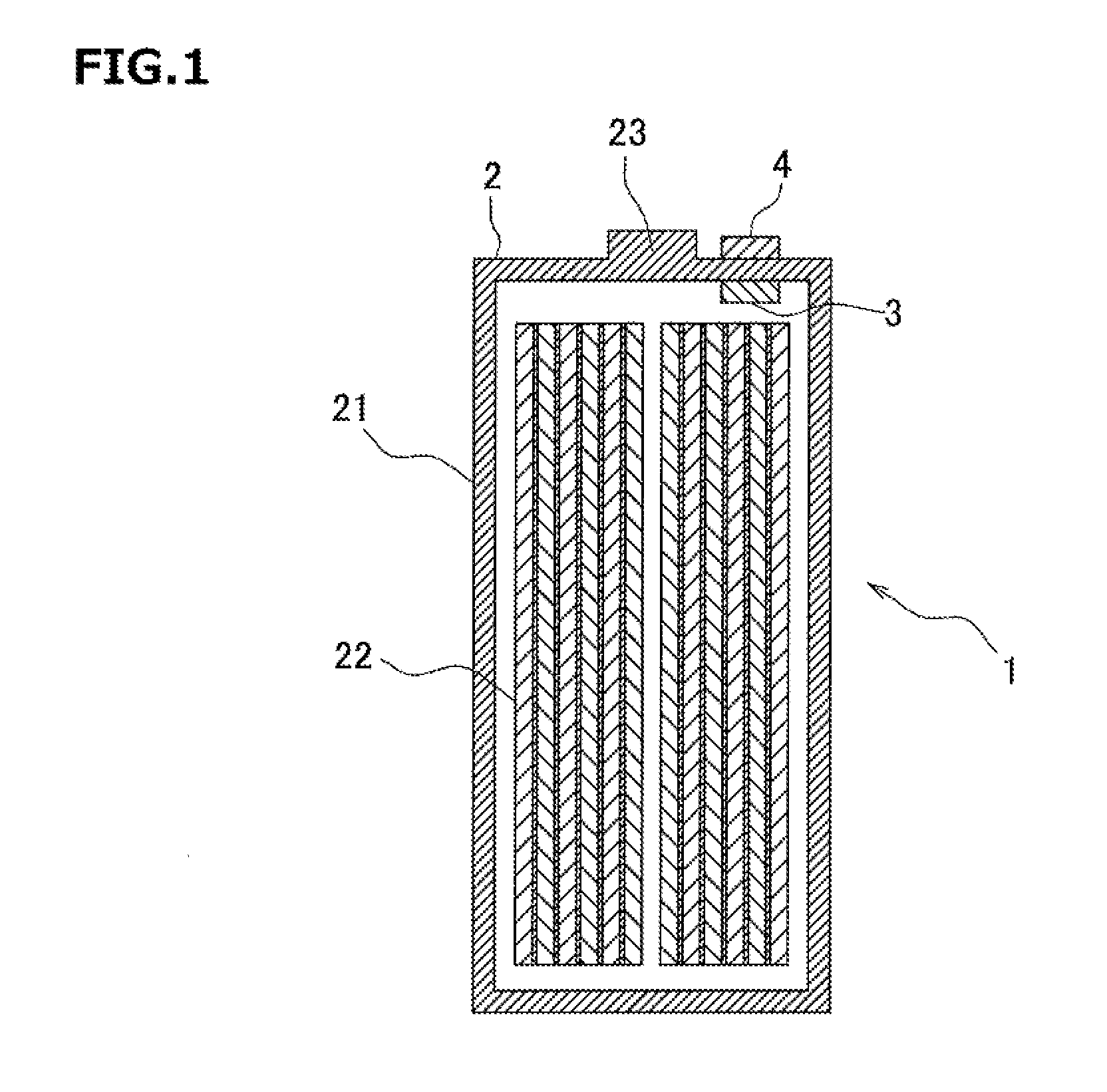
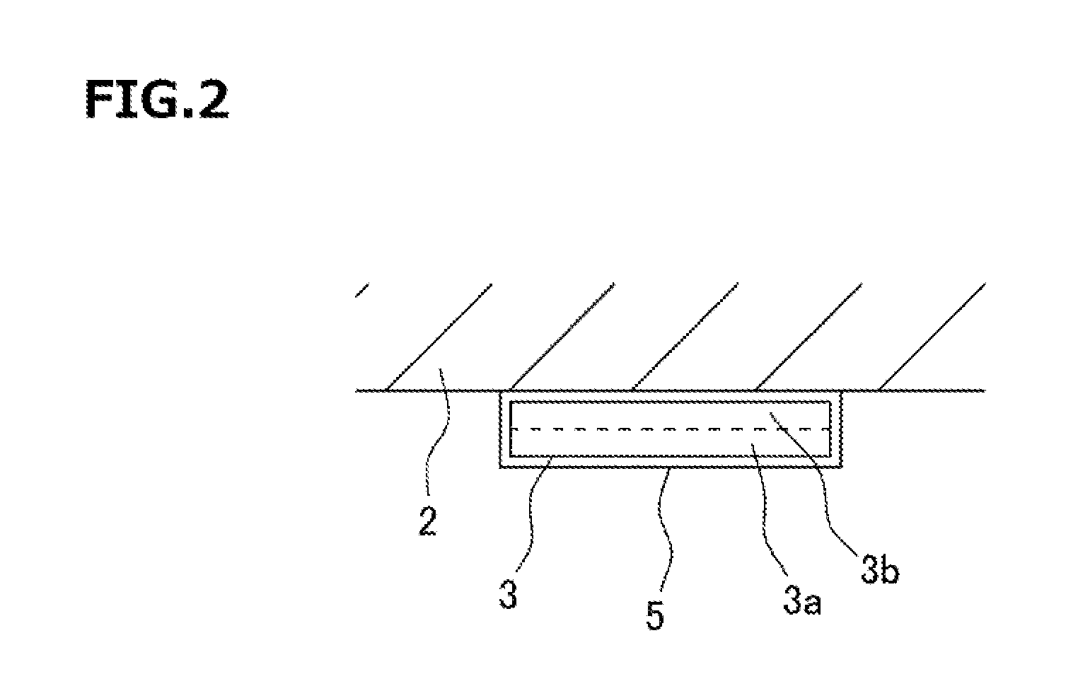
[0020]According to this method, when the internal pressure of the cell rises or when electrode swelling accompanying the charging and discharging increases, the polymer matrix layer is deformed in the inside of the outer casing in accordance therewith, and change in the external field accompanying the deformation of the polymer matrix layer is detected by the detection unit disposed on the outside of the outer casing. Because such a method of detecting change in the external field is adopted, there is no need for an electric wire from the polymer matrix layer to the defection unit, and therefore, the sealed structure is not hindered. Moreover, because the polymer matrix layer is disposed in the inside of the outer casing, the internal pressure change of the cell and the electrode swelling can be detected with a high degree of sensitivity.

Problems solved by technology

Such a secondary battery has a problem that, when the electrolytic solution is decomposed due to overcharging or the like, the cell swells to be deformed in accordance with rise in the internal pressure caused by the decomposition gas and, unless the charging current or the discharging current is stopped, this results in rupture of the secondary battery.
In order to cope with this problem, a safety valve is conventionally provided that is opened when an internal pressure comes to have a predetermined value or more (for example, about 1 to 2 MPa); however, this has another problem because the electrolytic solution is scattered to contaminate the surroundings when the safety valve is opened.
Therefore, unless a structure for sealing the surroundings of the electric wire is added, the sealed structure is hindered.
However, in this battery, detection is not carried out unless the internal pressure becomes so high that the welded part is peeled off.
Also, forming the part, in which the resin layer is absent or the metal layer is exposed at the welded part can disadvantageously be a cause of breakdown.

Method used


Image

  • Monitoring sensor for sealed secondary battery, sealed secondary battery, and monitoring method for sealed secondary battery
  • Monitoring sensor for sealed secondary battery, sealed secondary battery, and monitoring method for sealed secondary battery
  • Monitoring sensor for sealed secondary battery, sealed secondary battery, and monitoring method for sealed secondary battery

Examples


example 1

[0092]Into a reaction container, 40.0 parts by weight, of the polyol A (polyoxypropylene glycol obtained by adding propylene oxide to glycerin as an initiator, hydroxyl value of 56, number of functional groups being 3, manufactured by Asahi Glass Co., Ltd., EX-3030) and 40.0 parts by weight of the polyol B (polyoxypropylene glycol obtained by adding propylene oxide to propylene glycol as an initiator, hydroxyl value of 56, number of functional groups being 2, manufactured by Asahi Glass Co., Ltd., EX-2020) were put, and vacuum-dehydrated while being stirred for 1 hour. Thereafter, the inside of the reaction container was replaced with nitrogen. Subsequently, 20.0 parts by weight of p-MDI (diphenylmethane diisocyanate, manufactured by Nippon Polyurethane Industry Co., Ltd., MILLIONATE MTL) was added into the reaction container. While keeping the temperature of the inside of the reaction container at 80° C., the reaction was carried out for 3 hours to synthesize an isocyanate-terminat...

examples 2 to 7

[0094]Magnetic polyurethane resins were obtained in the same manner as in Example 1 on the basis of the blended components and production conditions shown in Table 2.

example 8

[0095]A filler dispersion liquid was prepared by adding 476.0 parts by weight of a neodymium-based filler (manufactured by Aichi Steel Corporation, MF-15P, average particle size of 133 μm) into a mixture liquid of 100.0 parts by weight of the above prepolymer A, 5.0 parts by weight of a silicone-based foam stabilizer (manufactured by Dow Corning Toray Co., Ltd., L-5340), and 0.42 part by weight of bismuth octylate (manufactured by Nippon Chemical Industrial Co., Ltd., BTT-24). This filler dispersion liquid was subjected to vigorous primary stirring for 5 minutes so as to take bubbles into the reaction system by using a stirring blade at a rotation number of 1000 rpm. Thereafter, 80.0 parts by weight of the above polyol A was added, and the resultant was subjected to secondary stirring for 3 minutes to prepare a bubble dispersion urethane composition containing the magnetic filler.

[0096]The above bubble dispersion urethane composition was dropped onto a PET film which had been subjec...


PUM

PropertyMeasurementUnit
elastic modulusaaaaaaaaaa
internal pressureaaaaaaaaaa
elastic modulusaaaaaaaaaa

Abstract

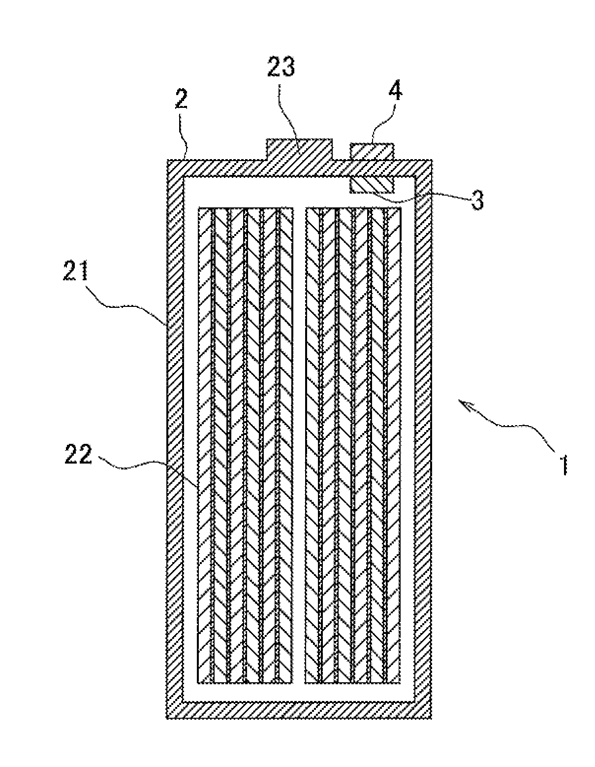
A monitoring sensor for a sealed secondary battery 1 including a sealed outer casing 21 and an electrode group 22 including a polymer matrix layer 3 that is disposed in the inside accommodated in the inside of the sealed outer casing 21, of the outer casing 21 and a detection unit 4 that is disposed on the outside of the outer casing 21, wherein the polymer matrix layer 3 contains a filler that is dispersed therein and that changes an external field in accordance with deformation of the polymer matrix layer 3, and the detection unit 4 detects change in the external field.

Description

TECHNICAL FIELD[0001]The present invention relates to a sensor for monitoring an inside state of a sealed secondary battery, a sealed secondary battery on which the sensor is mounted, and a method for monitoring an inside state of a sealed secondary battery.BACKGROUND ART[0002]In recent years, a sealed secondary battery (which may be hereinafter simply referred to as “secondary battery”) represented by a lithium ion secondary battery is used as a power source not only for a mobile apparatus such as a portable phone or a notebook personal computer but also for an electrically driven vehicle such as an electric automobile or a hybrid car. A cell constituting the secondary battery has a structure in which an electrode group is accommodated in an inside of a sealed outer casing, and the electrode group is constructed by winding or stacking a positive electrode and a negative electrode with a separator interposed therebetween. Generally, a laminate film such as an aluminum laminate foil ...

Claims


Application Information

Patent Timeline
Patent Type & Authority Applications(United States)
IPC IPC(8): H01M10/48G01L9/14G01R31/36H01M50/159H01M50/16H01M50/162H01M50/164
CPCH01M10/48G01L9/14G01R31/3679G01B7/24H01M10/0525H01M2200/20Y02E60/10H01M50/107Y02P70/50H01M50/159H01M50/162H01M50/16H01M50/164H01M10/425G01L11/00H01M50/124H01M10/34G01R31/392
Inventor FUKUDA, TAKESHIMINAKATA, NOBUYUKI
Owner TOYO TIRE & RUBBER CO LTD
Why Eureka
Try Eureka