Casing of implantable device and implantable device, method for manufacturing casing of implantable device, and method for supporting treatment using implantable device

a technology for implantable devices and casings, which is applied in the field of implantable devices, and the method of manufacturing casings of implantable devices, which can solve the problems of establishing any implantable technology, bulging of devices, and undesirable appearance, and achieves excellent safety, sufficient strength, and sufficient strength.

Active Publication Date: 2017-02-23
OSAKA UNIV
View PDF7 Cites 9 Cited by
  • Summary
  • Abstract
  • Description
  • Claims
  • Application Information

AI Technical Summary

Benefits of technology

[0032]In the present invention, the outer convexity surface 30 matching the external shape of the resected skull 27 related to at least the craniotomy site 26 of the artificial bone 28 designed in accordance with the shape of the skull 29 of each person in order to fill the craniotomy site 26 is used as the casing of the implantable device 4. That is, the outer convexity surface 30 of the artificial bone 28 is provided with two functions: the original function of filling the craniotomy site 26 as the artificial bone 28 and a function of serving as the casing 16 of the implantable device 4.
[0033]This type of artificial bone 28 is originally intended to fill the craniotomy site 26. In particular, the outer convexity surface 30 made of a metal has sufficient strength to withstand an external shock or the like, as with the skull. Thus, according to the present invention, the casing 16 of the implantable device 4 that has sufficient strength to withstand an external shock or the like and that is excellent in safety and reliability can be obtained. This means that the implantable device 4 can be safely implanted in the head, helping increase the reliability of the implantable device 4.
[0034]Further, using, as the casing 16 of the implantable device 4, the outer convexity surface 30 of the artificial bone 28 matching the external shape of the resected skull 27 related to the craniotomy site 26 eliminates the possibility that the implantable device 4 implanted in the head may appear on the outer surface of the head. Further, since the outer convexity surface 30 of the artificial bone 28 matches the external shape of the resected skull 27 related to the craniotomy site 26, the craniotomy site 26 can be filled with the outer convexity surface 30 (casing 16) matching the shape of the skull 29 of each patient. Thus, the implantable device 4 can be implanted in the head without bulging of the skin by the implantable device and without causing an uncomfortable feeling in terms of appearance. As seen, according to the present invention, the casing 16 of the implantable device 4 that resolves the patient's appearance impairment problem and that is excellent in practical utility can be provided. Further, the occurrence risk of complications such as a skin fistula caused by contact or friction with the bulging skin site can be reduced.
[0035]A configuration may be used where the artificial bone 2...

Problems solved by technology

However, a casing larger than the casing-implanted body site causes such as bulging of the device-implanted site seen from outside the body.
This is undesirable in terms of appearance.
Further, a contact or friction with the bulging skin easily ...

Method used


Image

  • Casing of implantable device and implantable device, method for manufacturing casing of implantable device, and method for supporting treatment using implantable device
  • Casing of implantable device and implantable device, method for manufacturing casing of implantable device, and method for supporting treatment using implantable device
  • Casing of implantable device and implantable device, method for manufacturing casing of implantable device, and method for supporting treatment using implantable device

Examples


first embodiment

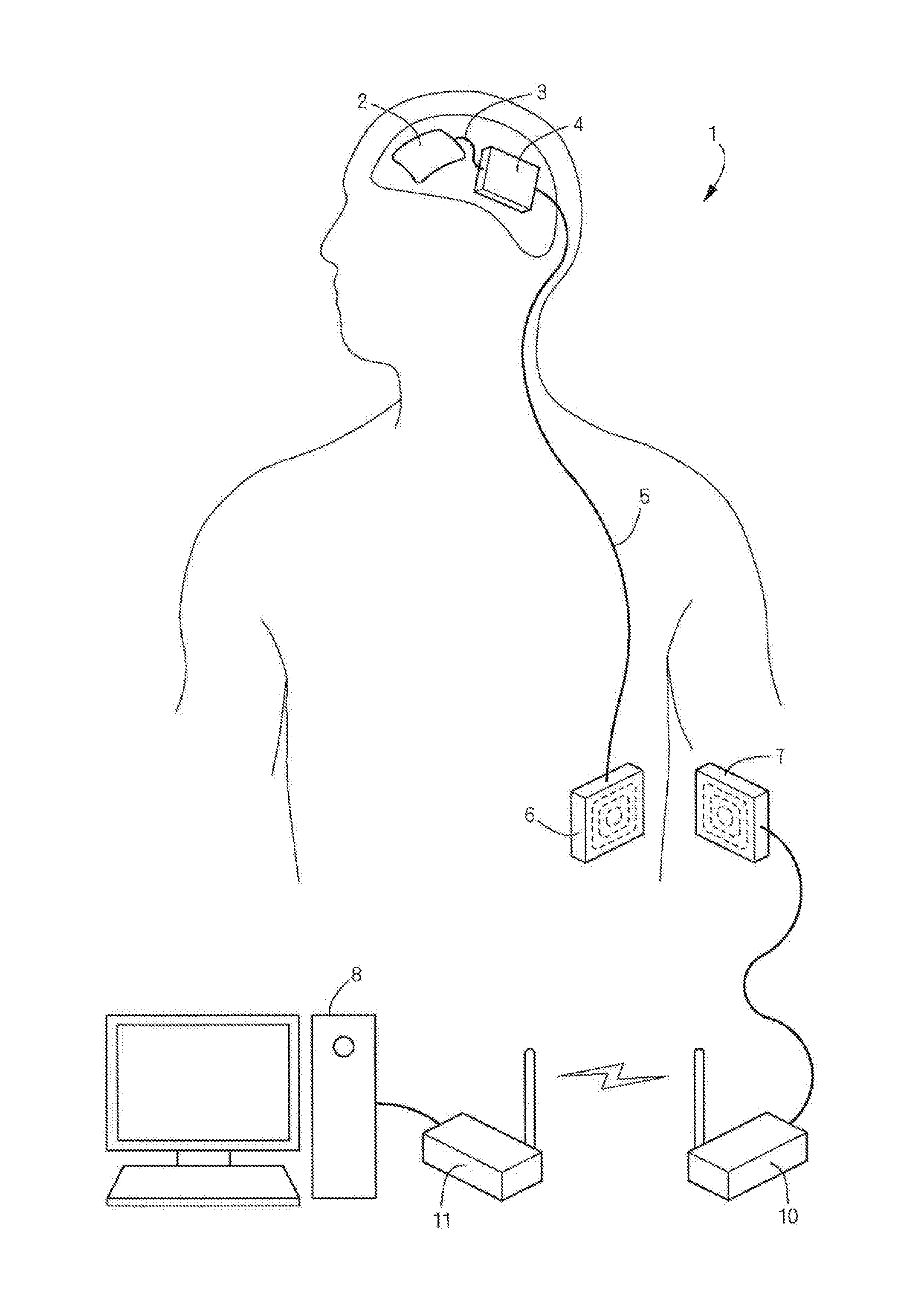
[0075]FIGS. 1 to 10 show an embodiment where an implantable device according to the present invention is applied to a brain signal measurement system. As shown in FIGS. 1 and 2, the brain signal measurement system 1 is a system for measuring electrocorticograms. It includes a sheet-shaped grid electrode array (function unit) 2 for brain signal (electrocorticogram) measurement, an implantable device 4 connected to the sheet-shaped grid electrode array 2 via an analog cable (cable) 3, an internal transceiver 6 connected to the implantable device 4 via a digital cable 5 and configured to be implanted subcutaneously in the abdomen, an external transceiver 7 wirelessly connected to the internal transceiver 6, and a personal computer (hereafter simply referred to as “computer”) 8 for neural signal processing. Signs 10, 11 represent wireless transceivers 10, 11 laid out between the external transceiver 7 and the computer 8 and forming a wireless LAN. The computer 8 receives a measurement r...

second embodiment

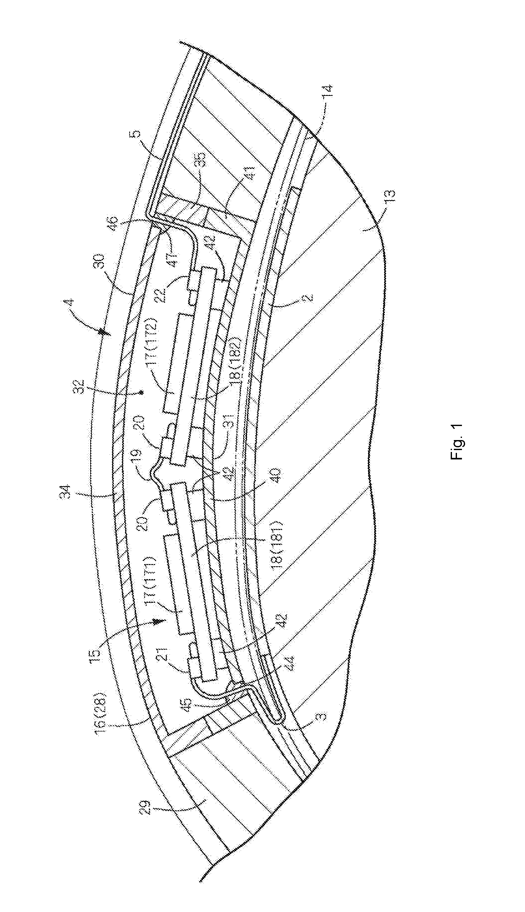
[0087]FIGS. 11 and 12 show a second embodiment of the present invention. The second embodiment differs from the first embodiment in the following point: in the case where when, in designing the layout using CAD, the skull shape of the patient is used as the shape of a casing outer convexity surface 30 as it is, an electronic circuit 15 cannot be laid out within internal space 32 of a casing 16, the outer convexity surface 30 is formed in a manner swelling out slightly outwardly (upwardly in the illustrated example) so as to secure internal space 32 sufficient to incorporate the electronic circuit 15 (FIG. 11). Further, the second embodiment differs from the above-mentioned first embodiment in that the top surfaces of fixing plates 36 are flush with the top surface of an external wall 34 and in that caving depressions 50 to which the fixing plates 36 are to be attached are formed on a skull 29 around a craniotomy site 26 in the shape of notches (FIG. 12). The second embodiment is the...

third embodiment

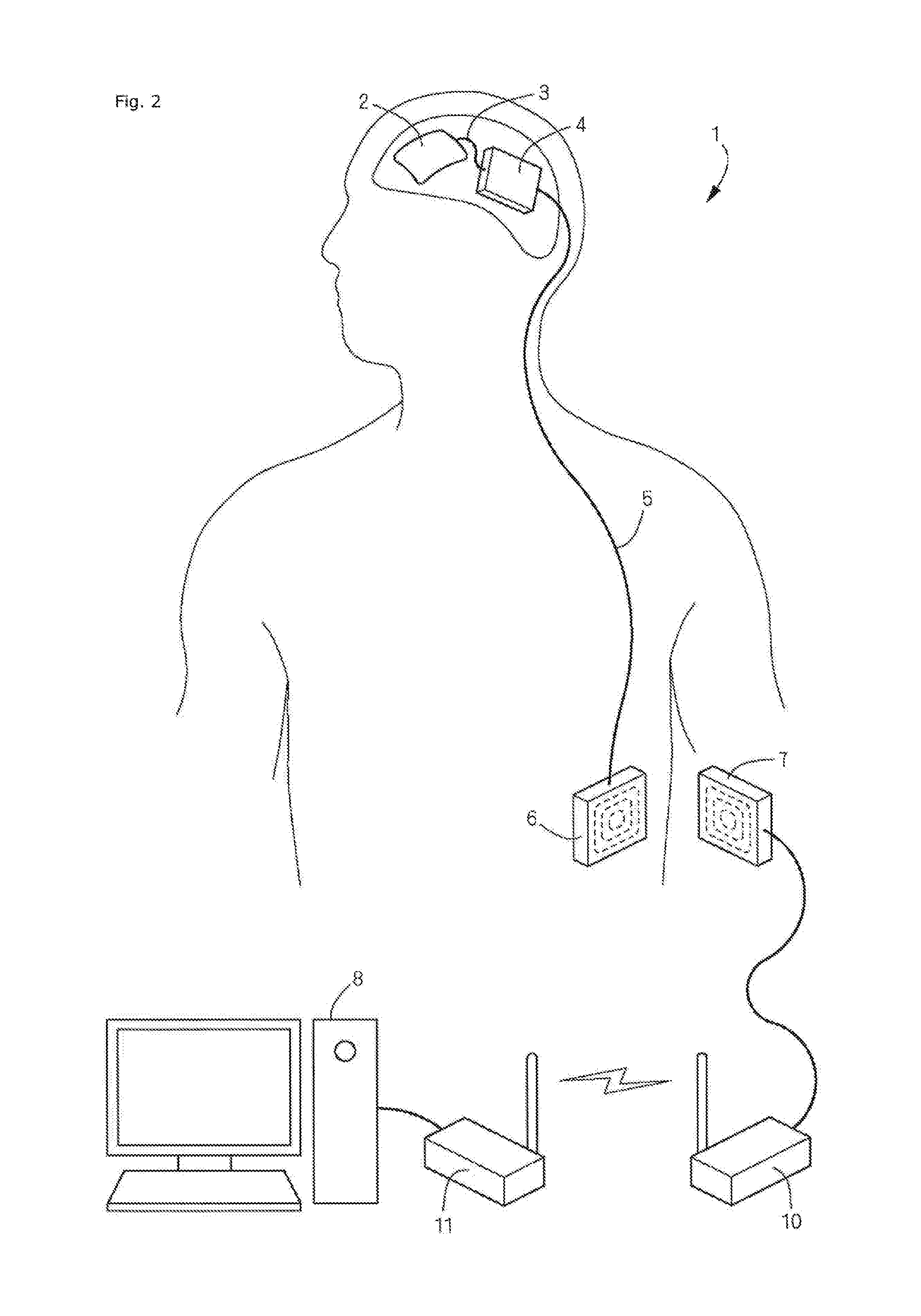
[0097]FIGS. 14 to 23 show a third embodiment where an implantable device according to the present invention is applied to a brain signal measurement system. This brain signal measurement system is similar to the system according to the above-mentioned first embodiment shown in FIG. 2. It includes a sheet-shaped grid electrode array (function unit) 2 for brain signal (electrocorticogram) measurement, an implantable device 4 connected to the sheet-shaped grid electrode array 2 via an analog cable (cable) 3, an internal transceiver 6 connected to the implantable device 4 via a digital cable 5 and implanted subcutaneously in the abdomen, an external transceiver 7 wirelessly connected to the internal transceiver 6, and a personal computer (hereafter simply referred to as “computer”) 8 for neural signal processing.

[0098]As shown in FIG. 14, the sheet-shaped grid electrode array 2 is disposed under the dural membrane. In this embodiment, it is fixed to the surface of a brain 13 (the surfac...


PUM


Abstract

To allow an implantable device including an electronic circuit to be implanted in the head in a more preferable manner in terms of appearance and safely. This implantable device is used for a brain-machine interface or the like. A casing of an implantable device configured to be implanted in a human head has an outer convexity surface matching an external shape of a resected skull related to at least a craniotomy site of the artificial bone designed in accordance with a skull shape of each person in order to fill the craniotomy site. That is, the outer convexity surface of the artificial bone is provided with two functions: the original function of filling the craniotomy site as the artificial bone and a function of serving as the casing of the implantable device.

Description

CROSS REFERENCE TO RELATED APPLICATIONS[0001]This application is a continuation-in-part application of and claims the benefit and priority to U.S. patent application Ser. No. 13 / 510,841, filed on Oct. 4, 2012, which claims the benefit and priority to and is a U.S. National Phase Application of PCT International Application Number PCT / JP2011 / 001402, filed on Mar. 10, 2011, designating the United States of America, which is an International Application of and claims the benefit of priority to Japanese Patent Application No. 2010-250464, filed on Nov. 9, 2010. The disclosures of the above-referenced applications are hereby expressly incorporated by reference in their entireties.BACKGROUND OF THE INVENTION[0002]Field[0003]The present invention relates to a casing of an implantable device configured to be implanted in a human body and an implantable device, a method for manufacturing a casing of an implantable device, and a method for supporting treatment using an implantable device.[000...

Claims


Application Information

Patent Timeline
IPC IPC(8): A61B5/00A61F2/28G06F3/01A61B5/0478
CPCA61B5/6868A61B5/0478A61F2/2875A61B2562/166A61B2562/0209A61B2562/222A61B2562/164G06F3/015A61N1/375A61N1/0531A61N1/37514A61N1/37518A61B5/291A61B5/293
Inventor HIRATA, MASAYUKIYOSHIMINE, TOSHIKIMATSUSHITA, KOJIROGOTO, TETSUYANAGISAWA, TAKUFUMISUZUKI, TAKAFUMIYOSHIMURA, SHINICHI
Owner OSAKA UNIV
Why Eureka
Try Eureka