Discharge head for a vertical pump and vertical pump

Inactive Publication Date: 2017-02-23
SULZER MANAGEMENT AG
View PDF2 Cites 5 Cited by
  • Summary
  • Abstract
  • Description
  • Claims
  • Application Information

AI Technical Summary

Benefits of technology

The invention is about improving the life time of a discharge head used in pumps. The invention has found that the section of the inner tube between the intersection and the top plate is exposed to very high thermal stress, which can bend the inner tube and cause strain on other components like the base plate, the top plate, and the support member. To address this problem, a bellows member is used to compensate different thermal expansions of the components, reducing the high stresses in the discharge head due to temperature differences and thermal transients. This results in a significantly improved life time of the discharge head even when subjected to a large number of thermal cycles. It is also preferred to reduce the thermal stress by connecting the discharge support only to the base plate and the horizontal section of the discharge pipe.

Problems solved by technology

The high temperature and the properties of the molten salt are a big challenge regarding an appropriate design of the vertical pump.
Another challenge is the considerable thermal stress which is due to the high temperature of the molten salt of up to 600° C. as compared to ambient temperature and thermal transients.
Thus, it may be that the vertical pump runs at idle for several hours so that the pump head cools down by losing heat to the environment.
Then, the restart of the pump results in a thermal shock of the discharge head.
These effects cause a considerable thermal load on the components of a vertical pump.
This bending places a significant strain both on the connection of the inner tube with the discharge pipe and on the connection of the inner tube with the top plate.
In addition, the bending may also result in a deformation of other components like the base plate, the top plate and the support member.

Method used


Image

  • Discharge head for a vertical pump and vertical pump
  • Discharge head for a vertical pump and vertical pump
  • Discharge head for a vertical pump and vertical pump

Examples


Embodiment Construction

[0035]In the drawings respective identical parts or parts having the same function or an analogously same function are designated with the same reference numerals.

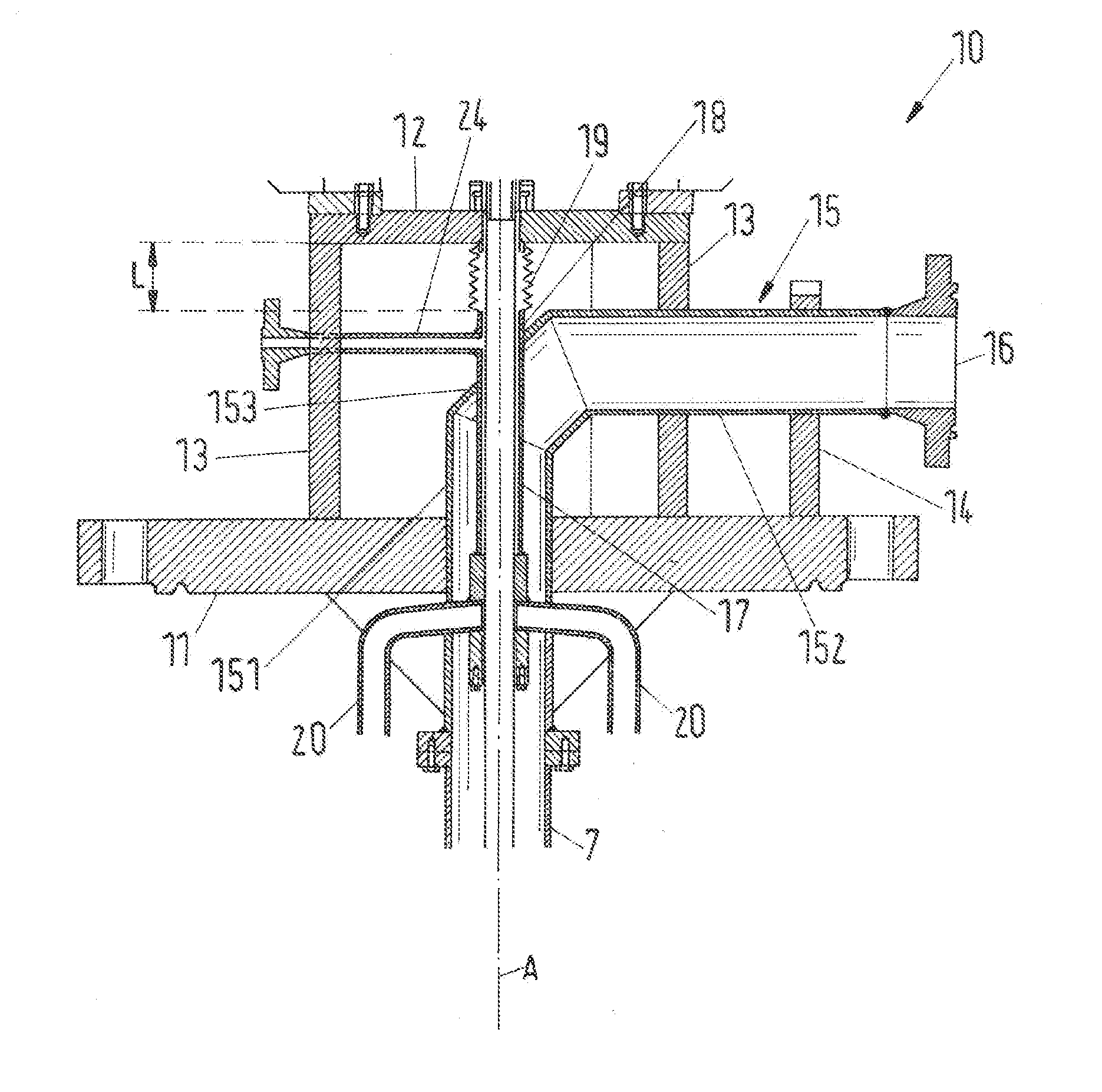
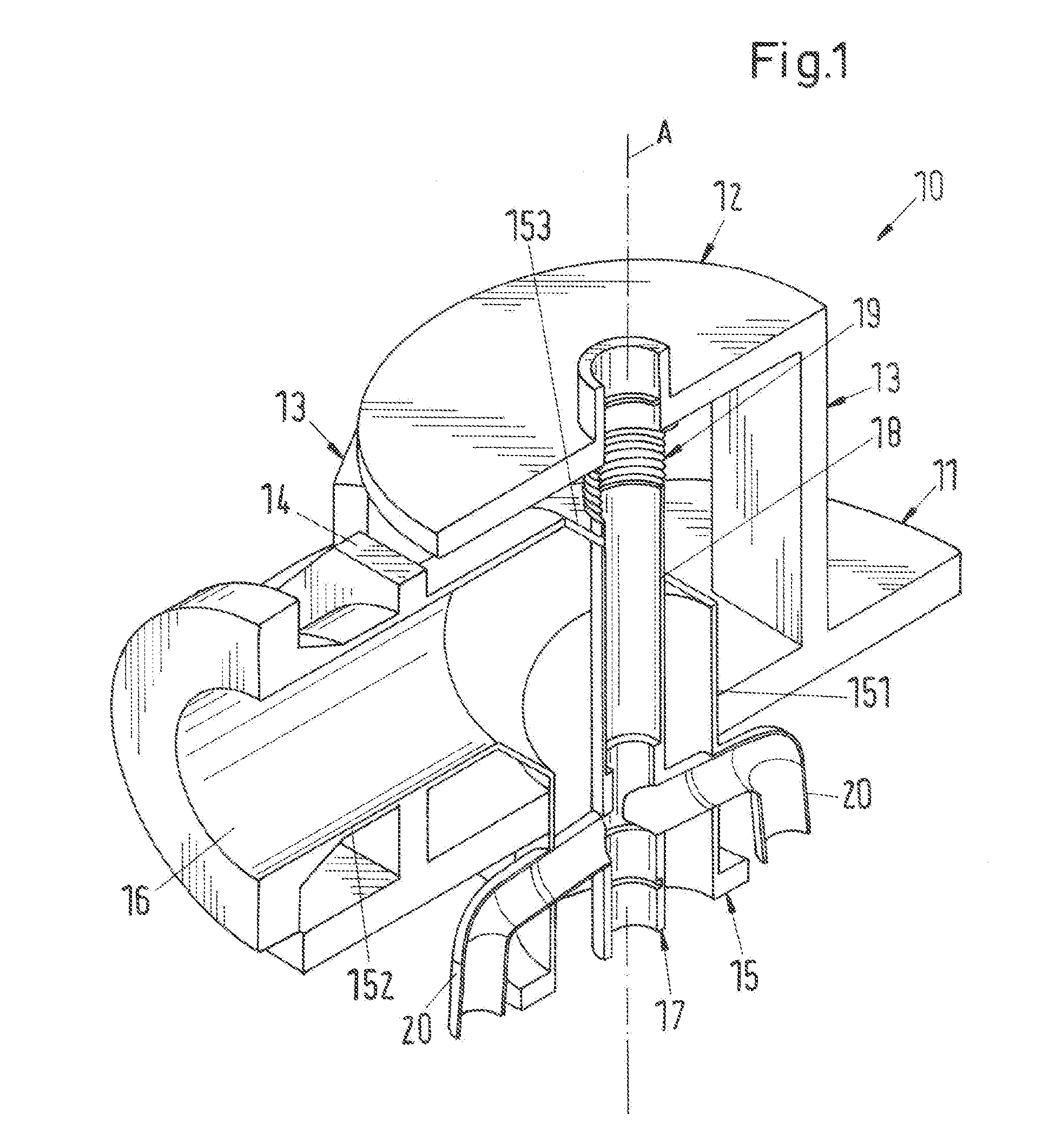
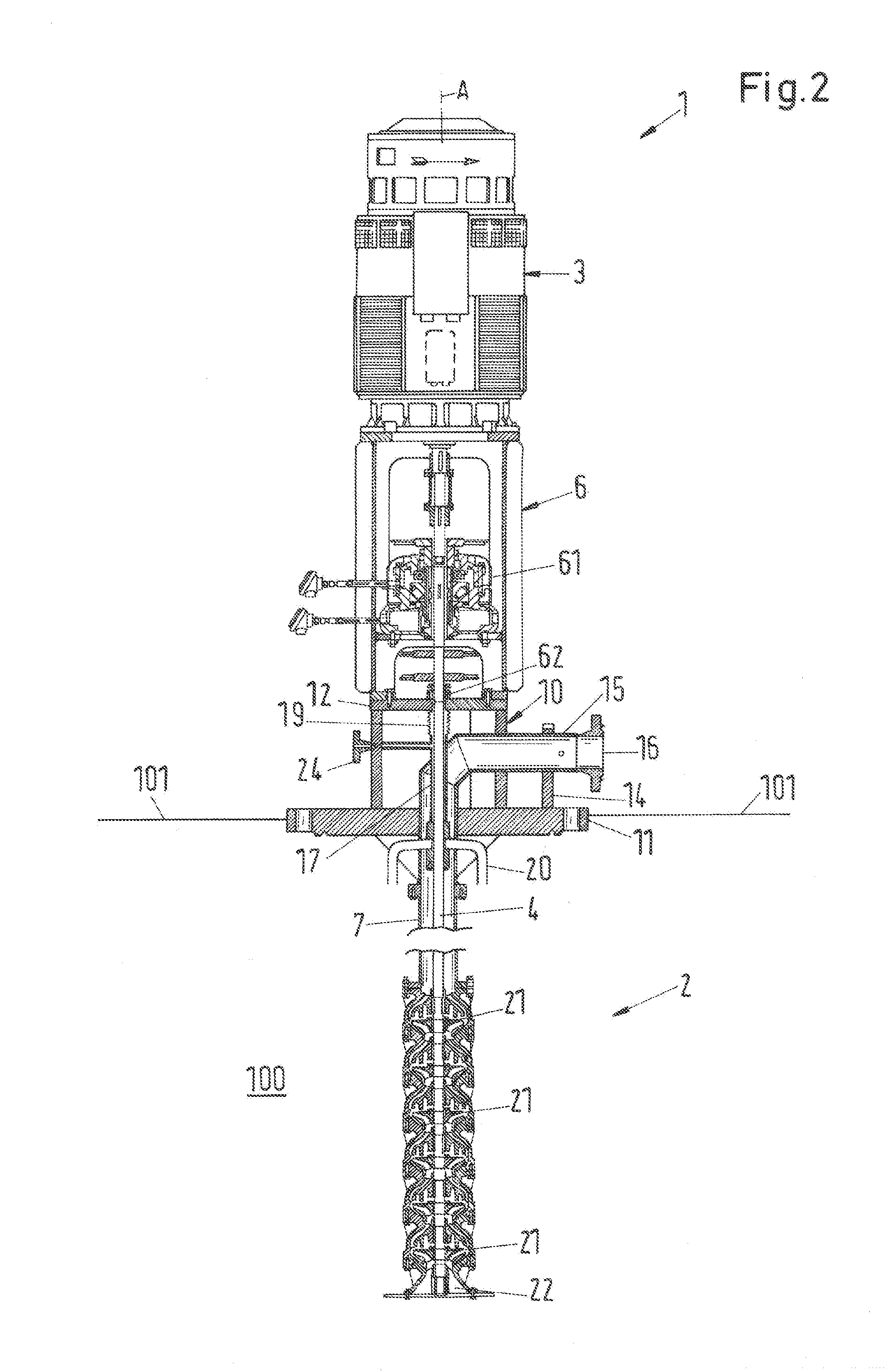
[0036]FIG. 1 shows a perspective, cross-sectional view of an embodiment of a discharge head for a vertical pump according to the invention. The discharge head is designated in its entity with reference numeral 10. FIG. 2 shows a cross-sectional view of an embodiment of a vertical pump according to the invention being designated in its entity with reference numeral 1 and comprising a discharge head 10 according to the invention.

[0037]In the following description reference is made by way of example to the important application that the vertical pump is designed and adapted for a solar energy system which is a concentrated solar power (CSP) system using molten salt as the heat transfer fluid (HTF) or as the heat storage fluid, respectively. More particular, in this example the vertical pump is mounted to a tank for molten sal...


PUM


Abstract

A discharge head for a vertical pump includes a base plate configured to mount the discharge head, a top plate, at least one support member connecting the base plate with the top plate, a discharge pipe with an outlet configured to deliver a fluid, and an inner tube. The discharge pipe extends through the base plate. The inner tube is configured to receive a shaft that connects a drive unit with an impeller of the vertical pump, and extends in an axial direction and coaxially within the discharge pipe in a region of the base plate, passing through a wall of the discharge pipe at an intersection, and further extending to the top plate. The inner tube includes a bellows member disposed between the intersection and the top plate.

Description

CROSS-REFERENCE TO RELATED APPLICATIONS[0001]This application claims benefit to U.S. Application No. 62 / 206,529, filed Aug. 18, 2015, the contents of which is hereby incorporated herein by reference.BACKGROUND[0002]Field of the Invention[0003]The invention relates to a discharge head for a vertical pump.[0004]Background of the Invention[0005]Vertical pumps have been used successfully in a plurality of applications for a very long time. Vertical pumps for specific applications are quite often manufactured in accordance with the specifications of the users or are matched in detail to specific requirements. Vertical pumps may be designed both as single stage and multistage pumps. They are typically immersed into the liquid reservoir to be pumped, so that at least the intake or suction bell with the adjoining pump rotor is immersed into the fluid to be pumped, so that the pump is directly ready for operation.SUMMARY[0006]One field of increasing importance for the use of vertical pumps i...

Claims


Application Information

Patent Timeline
IPC IPC(8): F04D29/42F04D1/06F04D29/046F04D29/22F04D29/043F04D7/06F04D13/14
CPCF04D29/4293F04D7/06F04D1/06F04D29/046F04D29/22F04D29/043F04D13/14F04D29/007F05D2260/941F04D13/08F04D29/426F05D2230/642F05D2260/602F04D29/406F04D13/06
Inventor GORDON, JEFFREY
Owner SULZER MANAGEMENT AG
Why Eureka
Try Eureka