
Method and apparatus for three-dimensional fabrication

a three-dimensional object and fabrication method technology, applied in the direction of additive manufacturing, manufacturing tools, additive manufacturing, etc., can solve the problems of difficult production of large objects such as automotive parts by additive manufacturing techniques, high cost of resins, and relatively short “pot li

Active Publication Date: 2017-03-09
CARBON INC
View PDF4 Cites 25 Cited by
  • Summary
  • Abstract
  • Description
  • Claims
  • Application Information

AI Technical Summary

Benefits of technology

The present invention provides a method for making a three-dimensional object using an apparatus including a radiation source, a carrier, a movable belt, and a polymerizable liquid. The method involves applying the polymerizable liquid to the belt, using the belt to adhere the liquid to the carrier or object, and then polymerizing the liquid using actinic radiation. The polymerization inhibitor passes through the belt to form an active surface on the object, which allows for continuous covalent coupling of new material to previously deposited material. The invention also provides an apparatus for making a three-dimensional object with the necessary components included in a single head assembly.

Problems solved by technology

Production of large objects such as automotive parts by additive manufacturing techniques has been challenging.
Some approaches, such as “bottom up” three-dimensional fabrication, require resin to flow longer distances through the narrow space between the growing object and the resin source during fabrication of larger objects: A particular problem with viscous resins and solid objects.
Other approaches, such as “top down” three-dimensional fabrication, require larger objects to be lowered into larger baths or reservoirs of the resin during fabrication: A particular problem with resins that are expensive, and / or have a relatively short “pot life.”
This, however, does not solve the problem of placing large amounts of potentially expensive, and in some cases short pot-life, materials in a large vat or open space (see also L. Goreta, PCT Application WO 1995 / 15841, and A. Allanic, PCT Application WO 2014 / 108473).

Method used


Image

  • Method and apparatus for three-dimensional fabrication
  • Method and apparatus for three-dimensional fabrication
  • Method and apparatus for three-dimensional fabrication

Examples


example 1

Example Apparatus

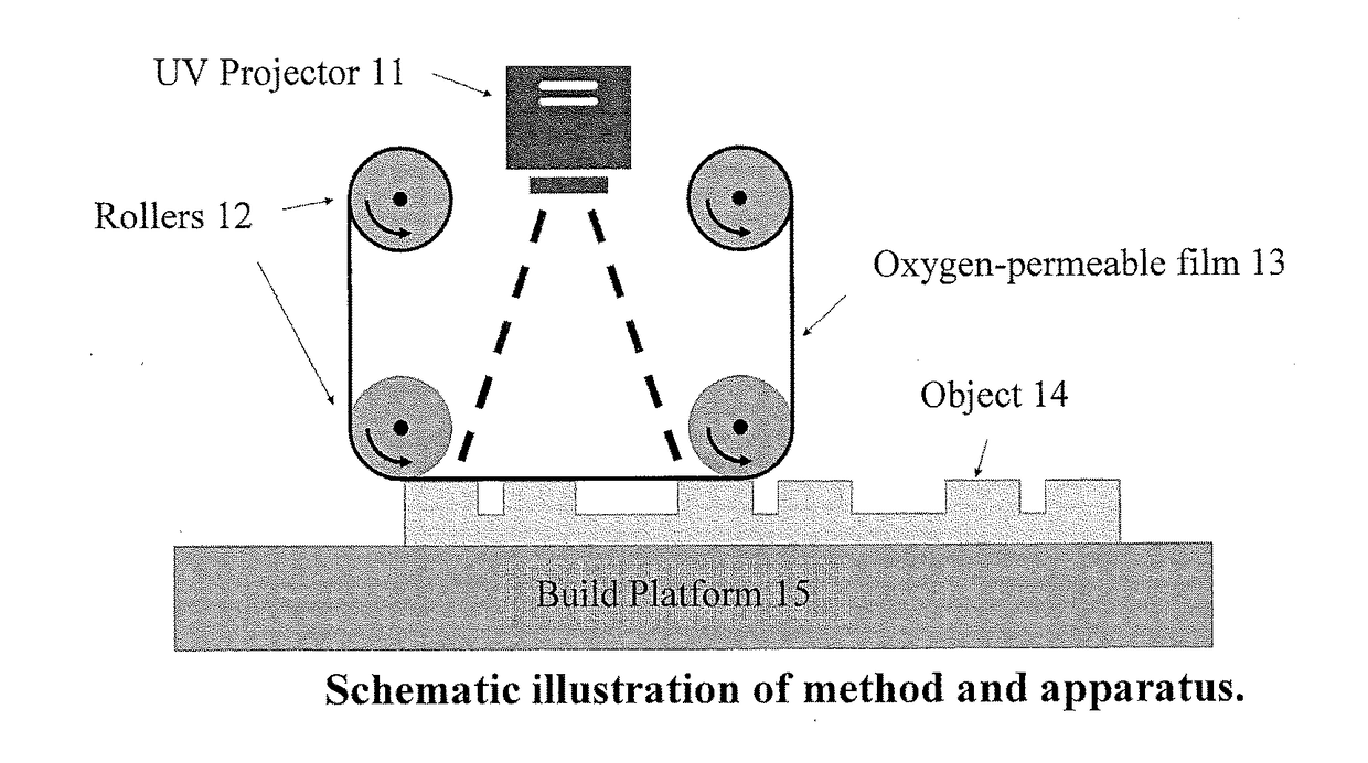
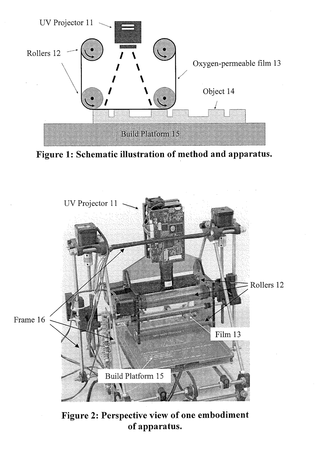
[0132]A first embodiment of an apparatus (FIG. 2) of the invention was built around a “Rep-Rap” frame 16, which provides single-axis motion of the build platform 15, and up-down motion for the light source 11, belt 13, and a roller assembly 12 on which a belt is mounted. The belt was created from a TEFLON® fluorinated ethylene propylene film, CS Hyde Item No. 23-3FEP-24 (CS Hyde Co., 1351 N. Milwaukee Ave., Lake Villa, Ill. 60046 USA). The roller assembly included a set of stepper motors and rollers which cause the belt to roll along the assembly. A WINTECH PRO4500 ultraviolet digital light projector (available from Wintech Digital Systems Technology Corp., 2888 Loker Ave. East, STE210C, Carlsbad, Calif. 92010 USA), was mounted onto the assembly, projecting an image onto the belt window formed by the orientation of the belt and the roller assembly. In this embodiment, resin is applied to the part manually before rolling the film over the part and exposing each layer...

example 2

Fabrication of Three-Dimensional Objects

[0133]A UV-curable resin comprised of 76 parts Sartomer CN2920, 5 parts isobornyl acrylate, 19 parts cyclohexanedimethanol divinyl ether, 0.5 parts Irgacure 819 photoinitiator, 0.04 parts Wikoff SCUV 14607 Black, and 0.16 parts Wikoff SCUV 14611 White was provided.

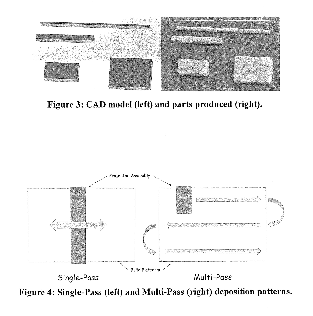
[0134]A test fabrication was performed using the resin was carried out with the apparatus of Example 1, with a slice height of 100 microns and manual application of the resin to the film on each pass. Results are shown in FIG. 3. Not including manual resin application (which will be automated in future revisions and add minimal time), each layer took approximately 1.5 seconds (0.5 second exposure, 1 second move). With a slice height of 100 microns, this correlates to a fabrication speed of approximately 240 millimeters per hour.

example 3

Mounting of Head Assembly to CNC Machine as Second Drive Assembly

[0135]A “head assembly” apparatus comprising a source of actinic radiation, belt to which polymerizable liquid is applied, applicator for applying the polymerizable liquid to the belt, and associated interconnecting frame, as described above, is mounted or retrofitted to a commercial vertical or horizontal CNC machine (which then serves as the second drive assembly) to provide high accuracy, long distance, travel in various axes over a working bed or carrier for the object. Examples of suitable CNC machines include, but are not limited to, the HAAS VF-2, VF-4, and VF-12 / 40 vertical CNC machines, and the HAAS EC-400 and EC-400 horizontal CNC machines, available from Haas Automation, Inc., 2800 Sturgis Rd., Oxnard, Calif., 93030 USA.


PUM

PropertyMeasurementUnit
viscosityaaaaaaaaaa
viscosityaaaaaaaaaa
viscosityaaaaaaaaaa

Abstract

A method of making a three-dimensional object is carried out by: (a) providing an apparatus comprising a radiation source, a carrier on which the three dimensional object is made, and a movable belt positioned therebetween, the belt having a first surface and an opposite second surface, with the belt comprised of an optically transparent material, and with the belt permeable to a polymerization inhibitor; (b) applying a polymerizable liquid to the first surface of the belt, and contacting the second surface of the belt to the polymerization inhibitor, (c) contacting a portion of the belt first surface having the polymerizable liquid thereon to the carrier or the three dimensional object so that the belt adheres thereto with the polymerizable liquid positioned therebetween; (d) irradiating the polymerizable liquid with actinic radiation through the belt from the radiation source to polymerize the polymerizable liquid positioned therebetween; then (e) optionally separating the belt from the carrier or the three dimensional object; and then (f) repeating steps (b) through (e) until the three dimensional object is completed. Apparatus for carrying out the method is also described.

Description

RELATED APPLICATIONS[0001]This application claims the benefit of U.S. Provisional Patent Application Ser. No. 62 / 216,014, filed Sep. 9, 2015, the disclosure of which is incorporated by reference herein in its entirety.FIELD OF THE INVENTION[0002]The present invention concerns methods and apparatus for the fabrication of three-dimensional objects, particularly larger objects, from hardenable materials.BACKGROUND OF THE INVENTION[0003]Production of large objects such as automotive parts by additive manufacturing techniques has been challenging.[0004]Some approaches, such as “bottom up” three-dimensional fabrication, require resin to flow longer distances through the narrow space between the growing object and the resin source during fabrication of larger objects: A particular problem with viscous resins and solid objects.[0005]Other approaches, such as “top down” three-dimensional fabrication, require larger objects to be lowered into larger baths or reservoirs of the resin during fab...

Claims


Application Information

Patent Timeline
Patent Type & Authority Applications(United States)
IPC IPC(8): B29C67/00B33Y30/00B33Y10/00
CPCB29C67/007B33Y30/00B33Y10/00B29C67/0092B29C64/129B29C64/194
Inventor ERMOSHKIN, ALEXANDERERMOSHKIN, NIKITAPINSCHMIDT, JR., ROBERT K.POLIZZI, ZACHARYRADEMACHER, SORENSHIRVANYANTS, DAVIDSAMULSKI, EDWARD T.
Owner CARBON INC
Learn More