
Ion Concentration Polarization-Electrocoagulation Hybrid Water Treatment System

a technology of electrocoagulation and hybrid water treatment, applied in water/sewage treatment by electrochemical methods, electrodialysis, membranes, etc., can solve problems such as difficulty in scale-up, ph changes near electrodes, chemical reactions, etc., to reduce membrane fouling, high energy input, and performance largely

Active Publication Date: 2017-03-09
MASSACHUSETTS INST OF TECH
View PDF0 Cites 12 Cited by
  • Summary
  • Abstract
  • Description
  • Claims
  • Application Information

AI Technical Summary

Benefits of technology

The patent describes a hybrid system that can treat various types of wastewater by removing salt and particles. The system involves a single electrochemical system that can simultaneously remove nonionic particles and desalinate water. By using shared electrodes for the two processes, the system reduces energy consumption and unnecessary voltage drop. The technical effect of this invention is an efficient and flexible treatment for various types of wastewater.

Problems solved by technology

Two disadvantages of this technology include chemical reactions and pH changes near electrodes and difficulties in scale-up[3].

Method used


Image

  • Ion Concentration Polarization-Electrocoagulation Hybrid Water Treatment System
  • Ion Concentration Polarization-Electrocoagulation Hybrid Water Treatment System
  • Ion Concentration Polarization-Electrocoagulation Hybrid Water Treatment System

Examples


Embodiment Construction

[0050]A description of preferred embodiments of the invention follows.

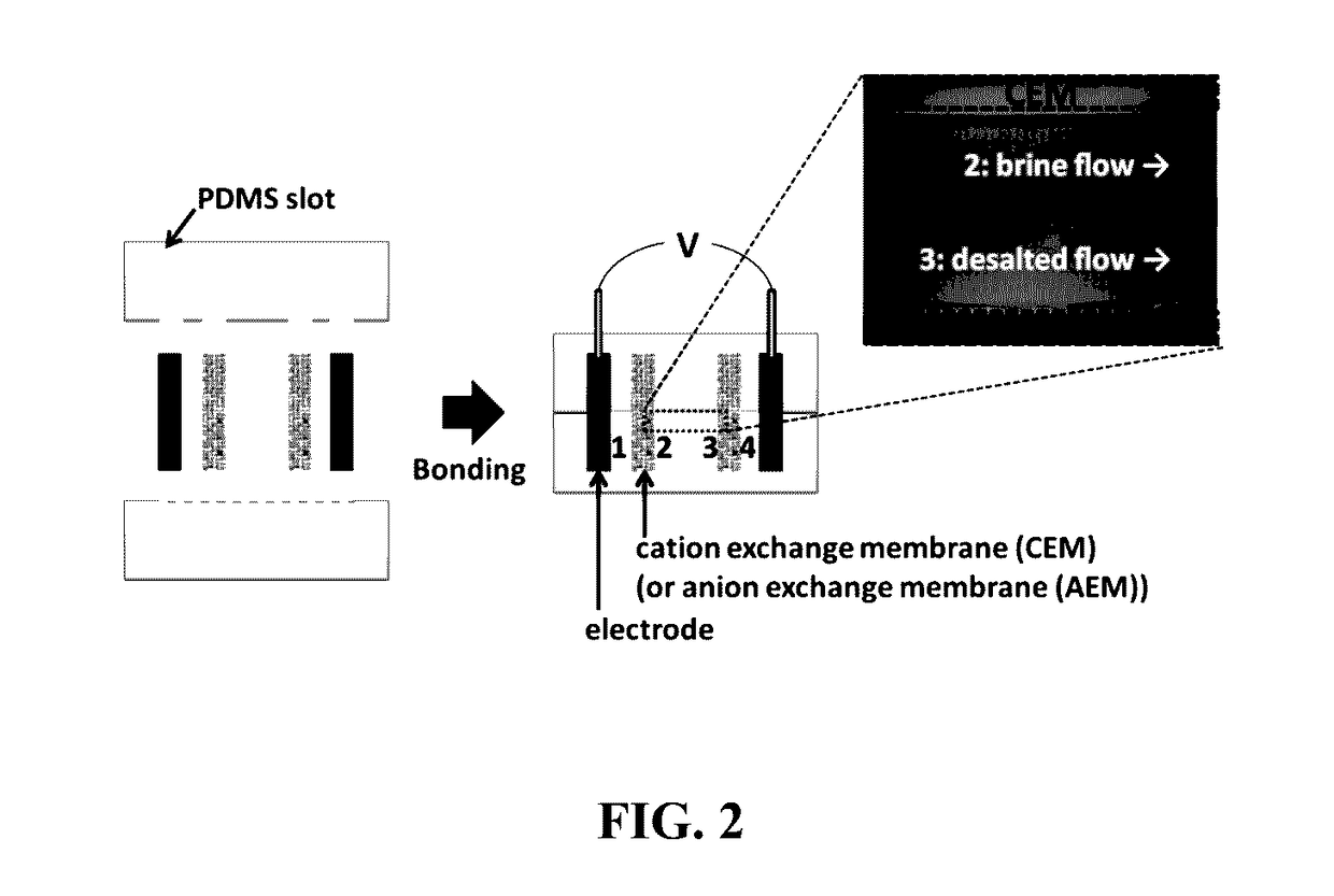
[0051]To demonstrate and characterize desalination / purification of the new platform, the sample device is fabricated by slotting IEMs and electrodes into Polydimethylsiloxane (PDMS) (FIG. 2). In 10 mM NaCl solution as a model of brackish water, fluorescent dye (Alexa Fluor 488, Invitrogen, Carlsbad, Calif.) is added to visualize ICP phenomenon. FUMASEP® FTAM-E, FTCM-E (FuMA-Tech CmbH, Germany), and carbon paper (Fuel Cell Store, Inc., Boulder, Colo.) are used as an AEM, CEM, and electrodes respectively. The detailed fabrication and operating procedures are same described in the Kwak et al. [4], incorporated herein by reference.

[0052]FIG. 3A shows the current-voltage curves and visualized ICP with fluorescent dyes between two CEMs. Typically, current-voltage response can be categorized as Ohmic (0-3 V), limiting (3-4.5 V) and overlimiting (>5 V) regimes[4]. As described by conventional convective-diffusion model[2]...


PUM

PropertyMeasurementUnit
lengthaaaaaaaaaa
lengthaaaaaaaaaa
inter-membrane distanceaaaaaaaaaa

Abstract

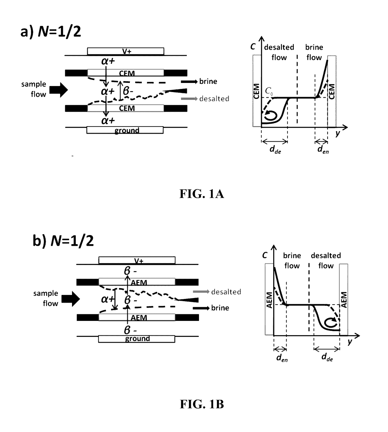
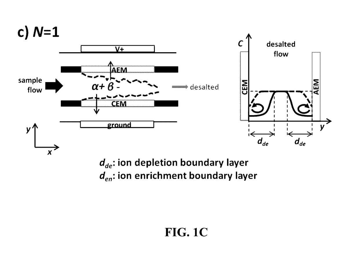
Between two juxtaposed similar ion exchange membranes (AEMs or CEMs), an ion depletion zone and ion enrichment zone are generated under an electric field. As cations are selectively transferred through the CEMs, for example, anions are relocated in order to achieve electro-neutrality, resulting in the concentration drop (increase) in ion depletion (enrichment) zone. The use of a sacrificial metal anode allows electrocoagulation (EC) concurrently with ICP thereby permitting concentration of both ionic and non-ionic impurities to occur at the same time within the same cell or device.

Description

RELATED APPLICATIONS[0001]This application is a continuation-in-part of U.S. application Ser. No. 14 / 306,607 filed on Jun. 17, 2014, which claims the benefit of U.S. Provisional Application No. 61 / 836,756, filed on Jun. 19, 2013. The entire teachings of the above applications are incorporated herein by reference.GOVERNMENT SUPPORT[0002]This invention was made with government support under Contract No. 6927935 and OSP Project No. 6927935 awarded by the Advanced Research Project Agency—Energy (ARPA-E). The government has certain rights in the invention.BACKGROUND OF THE INVENTION[0003]Fresh water is no longer considered a ‘free’ resource of nature. It is common knowledge that much of the freshwater sources in the world today are polluted and not adequate for human consumption. A bottle of clean, purified water is currently sold at a higher price than that of oil. Polluted drinking water creates various forms of water related diseases, such as anemia, arsenicosis, cholera, malaria, and...

Claims


Application Information

Patent Timeline
Patent Type & Authority Applications(United States)
IPC IPC(8): C02F1/463C02F1/46
CPCC02F1/463C02F1/4604C02F2303/18C02F2001/46133C02F2201/46115B01D61/42C02F1/469C02F2103/08B01D2311/2642B01D61/46B01D61/462B01D61/464
Inventor CHOI, SIWONHAN, JONGYOON
Owner MASSACHUSETTS INST OF TECH
Learn More