A method of mapping images of human disease and of designing or selecting a medical device using a surrogate model

a surrogate model and human disease technology, applied in the field of implantable medical devices, can solve the problems of failure, failure, failure or complications, and the limited range of stents available for implantation, and achieve the effect of improving the surrogate model

Active Publication Date: 2017-03-16
BRESSLOFF PROFESSOR NEIL +1
View PDF4 Cites 38 Cited by
  • Summary
  • Abstract
  • Description
  • Claims
  • Application Information

AI Technical Summary

Benefits of technology

[0032]In one embodiment, the estimates for the values of θl are obtained by maximising the concentrated In-likelihood function. In a further embodiment, an expected improvement calculation is used to determine further locations at which to obtain measured data points in order to improve the surrogate model.

Problems solved by technology

There are several problems associated with this approach.
The range of stents available for implantation may be limited to a small number of different stent designs.
Incorrect selection of a stent which is not the optimal stent for a specific patient from the provided range can cause complications and even failure.
Failure or complications can also occur if a stent with the optimal configuration for the type and shape of the diseased tissue is not available.
The location of the diseased tissue may also present complications.
For example, left main stem coronary bifurcation stents in particular have a relatively higher failure rate.
In this case, a stent of a standard off-the-shelf design may result in blocked side branches at the aneurysmal segment of the vessel, since the stents are covered in order to exclude the aneurysm itself.
However, it does not take into account the variation of the disease along the section of the artery in which the stent is to be located.

Method used


Image

  • A method of mapping images of human disease and of designing or selecting a medical device using a surrogate model
  • A method of mapping images of human disease and of designing or selecting a medical device using a surrogate model
  • A method of mapping images of human disease and of designing or selecting a medical device using a surrogate model

Examples


Embodiment Construction

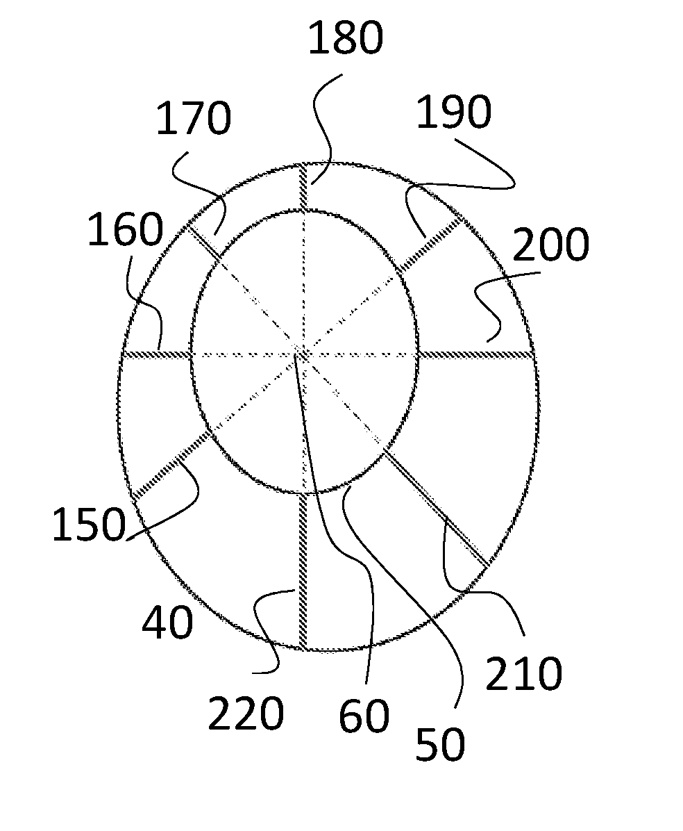
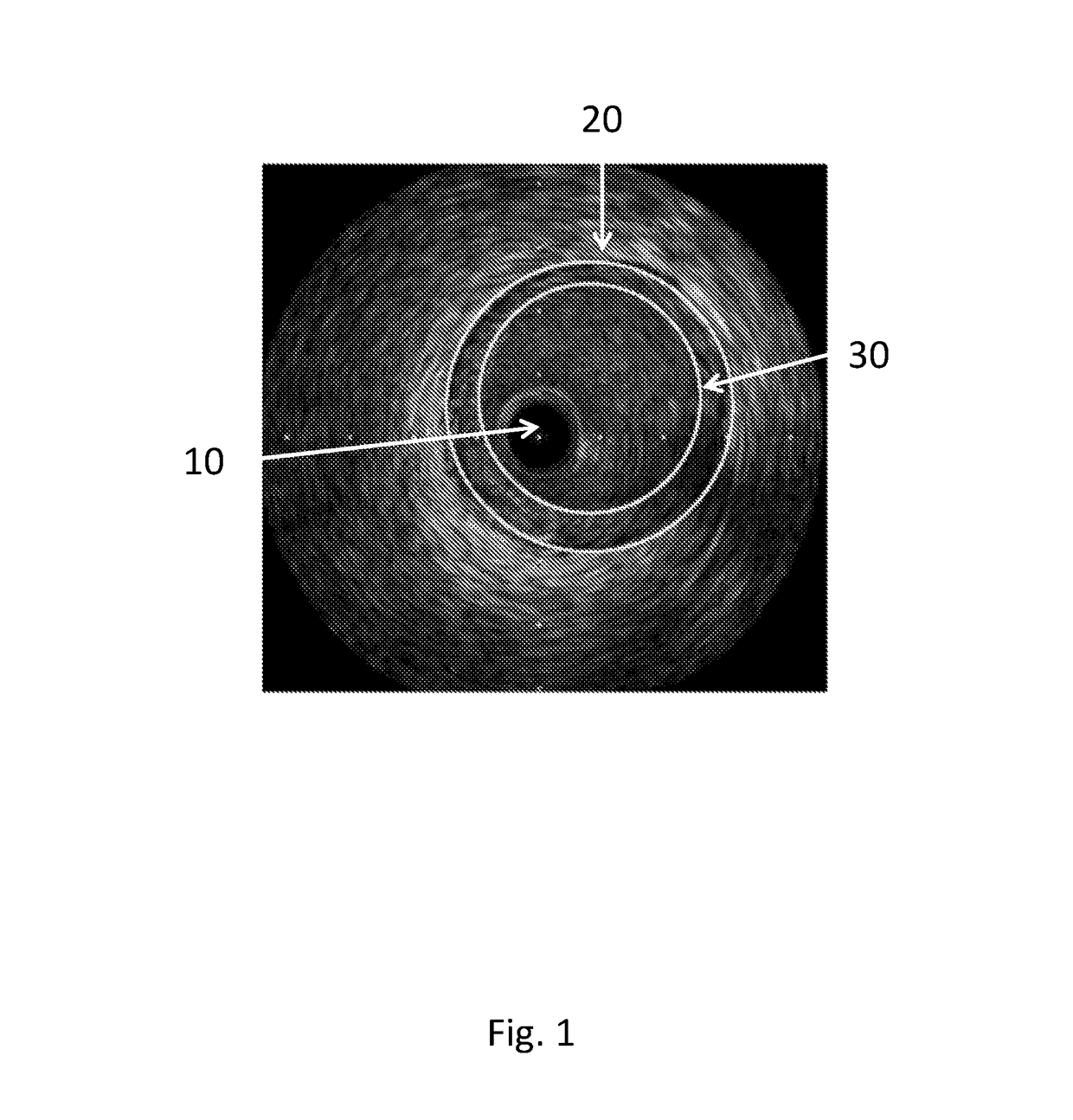
[0110]FIG. 1 depicts a section through a diseased coronary artery obtained using intravascular ultrasound (IVUS). The dark circular disc 10 in the centre of the image is the IVUS probe. Boundaries have been superimposed on the image approximately to define the lumen (inner boundary) 30 and the outer edge of the diseased tissue (outer boundary) 20, coinciding with the media. The media is the second of three identifiable layers in the arterial wall. It is bounded by the inner and outer elastic lamina and appears as a black ring on the IVUS image. It normally defines the outer edge of the plaque. The boundaries in this case are elliptical; however they can be irregularly shaped. The outer boundary is drawn to define the outer edge of the diseased tissue. The distance between the boundaries defines the thickness of the diseased tissue.

[0111]IVUS is performed using a catheter with an ultrasound probe which is inserted into the blood vessel. IVUS images are obtained during a pull-back sta...


PUM


Abstract

A method of designing or selecting an implantable medical device comprises the steps of: i) obtaining a plurality of measured data points of a characteristic of an anatomical feature of an individual; ii) using said data points to construct a surrogate model of said characteristic, the surrogate model being constructed by interpolating or regressing measured data points of the characteristic, and using said surrogate model to obtain predicted values of said characteristic at a plurality of locations; iii) using said predicted values to determine or select at least one value of a design parameter of the implantable medical device. There is further disclosed a method of monitoring or diagnosing a disease or disorder.

Description

FIELD OF THE INVENTION[0001]The present invention relates to implantable medical devices, methods of designing or selecting implantable medical devices, computer program products to execute methods of designing implantable medical devices, methods of manufacturing implantable medical devices and methods of monitoring or diagnosing diseases or disorders.BACKGROUND[0002]Implantable medical devices include devices such as stents, grafts, valves, filters and prosthetic implants such as hip implants used in hip replacement surgery. The devices are implanted into a patient and it is usually intended that they remain implanted in the patient permanently. The implanted device is often chosen from a standard range of available sizes and shapes based on patient specific anatomy.[0003]A stent is a deformable tubular structure which can be inserted into a vessel or passage in the body of a patient. For example, when an artery has become narrowed or constricted, an arterial stent can be implante...

Claims


Application Information

Patent Timeline
Patent Type & Authority Applications(United States)
IPC IPC(8): G06F17/50G06F19/00A61B8/08G06F17/11A61B6/00A61B8/12G16Z99/00
CPCG06F17/50A61B6/504A61B8/12G06F19/3437A61B8/5215A61B6/5211G06F17/11A61B8/0891A61B8/483A61F2/915A61B2017/00526A61F2240/002A61F2250/0018A61F2002/91533A61F2002/91575A61B34/10G16H50/50G16Z99/00G06F30/00
Inventor BRESSLOFF, NEIL W.
Owner BRESSLOFF PROFESSOR NEIL
Why Eureka
Try Eureka