System and method for minimally invasive injection foam

a technology of injection foam and system, which is applied in the field of system and a method for minimally invasive injection foam, can solve the problems of not coming close to achieving the energy use level of new buildings, reducing the number of new buildings built each year, and increasing the number of injection holes. , to achieve the effect of reducing the buildup of pressure, reducing the number of injection holes, and simplifying training

Inactive Publication Date: 2017-03-23
CERTAIN TEED LLC
View PDF14 Cites 7 Cited by
  • Summary
  • Abstract
  • Description
  • Claims
  • Application Information

AI Technical Summary

Benefits of technology

[0037]Among the advantages of the methods of this invention may be one or more of the following. Compared to direct methods of injecting foam, one or more aspects of the Minimally Invasive Injection method reduces the buildup of pressure on cavity walls, eliminates voids in cavities that contain fibrous insulation materials, provides consistent foam thickness, simplifies training, enables injection from either the inside or outside of a structure, minimizes the number of injection holes and reduces or eliminates subsequent repair processes. In addition to the advantages of these methods, the system eliminates the need to change nozzles frequently, improves the mix ratio of the various components of the foam, reduces costs of tubing, nozzles and other disposables, maximizes the distance between the cavity hole and the dispense location, enables workers to stay out of dangerous enclosed spaces and reduces complexity and variables involved in traditional spray foam equipment. In addition to the advantages of the system and methods, the materials described herein improve foam quality due to off ratio foam, reduce global warming potential, reduce cleanup, pose no respiratory risk for insulation workers and building occupants and eliminate hazardous waste disposal issues. Besides use in field application of insulation and for articles of manufacture, the methods, systems and materials described herein can be used to create insulation products for new construction that have lower cost, are easier to install and require less shelf space than traditional insulation products. Finally, the systems and methods described herein can be used in related applications such as application of polyurea coatings and epoxy structural adhesives.

Problems solved by technology

However, the number of new buildings built each year is only about 2% of the number of existing buildings.
However, most studies indicate that weatherization projects result in average energy savings of only 15% and don't come close to achieving the energy use levels of new buildings.
Because of the invasiveness of this process, the cost and time involved is very high.
Typical time to complete a deep energy retrofit of a house is several months and often requires building occupants to vacate the building.
Traditional deep energy retrofits are clearly not viable on a large scale.
Despite its tremendous potential, injection foam is rarely practiced.
One of the main issues is concern about the expanding foam “blowing out” walls.
This significant expansion combined with a compressive strength of 25 psi or more can easily cause existing plaster or drywall to bow out or completely detach from the framing.
While froth foams are generally preferred over pour foams, the packaging, metering and mixing of froth foams is problematic.
Foam in disposable pressure vessels are expensive to package and ship—costing about twice as much as two component pour foams—and have inadequate control over dispensed volume and mixing.
Re-usable pressure vessels are heavy, can't easily be moved around inside a building, and are exceedingly difficult for manufacturers to track.
However, large holes require extensive repair and repainting of the interior or exterior of the wall cavity.
A second, much more significant issue is that the vast majority of existing buildings already contain some insulation—typically fibrous insulation such as fiberglass—installed in the wall cavities.
The injection method described above can only be used on those few remaining uninsulated buildings with empty cavities.
Attempts to use the standard injection process with previously insulated buildings causes the foam to hang up in the fibrous insulation.
This in turn causes large gaps, inconsistent thickness and voids.
Besides these two significant problems with injection foam, two component insulating foams, both spray and injection, whether used for new construction or retrofit, suffer from many additional issues including:Worker Health and Safety Issues.
Nevertheless, during equipment maintenance or during material spills or other incidental exposures, workers can be exposed to isocyanates, one of the primary ingredients of the spray foam formulation.
These sensitivities can cause dangerous systemic reactions, including respiratory failure.
Furthermore, spray foam hose pressures are often in excess of 2000 pounds per square inch.
A rupture in one of these high pressure hoses can lead to dangerous high pressure chemical spray exposure.
High Cost and Complexity.
Equipment to process and apply spray foam usually costs well over $70,000.
The high costs of this equipment greatly limit the number of smaller businesses, Do-it-yourselfers and contractors that can take advantage of the improved insulation and moisture performance of foams.
Furthermore, the complexity of the equipment often leads to costly maintenance and downtime for insulation workers.
Foam insulation is also costly—materials typically cost 2 to 10 times more than fibrous insulation on a volumetric basis.
Poorly mixed foam can be caused by obstructions in mixing chambers, inconsistent pressures between the various components of the spray foam, poor temperature control of one or both materials, inconsistent material batches and other factors.
Foam that is not mixed at the proper ratio results in poor insulation performance, including air leaks, shrinkage and cracking, a strong “fishy” odor, deformation of the walls of the structure to which it is bonded, and delamination.
Because the thickness of the spray foam depends heavily on operator skill, obtaining consistent thickness from less experienced operators is difficult.
The inability of other trades to work on a building at the same time as spray foam insulators often causes unnecessary job site delays.
Time consuming application.
However, residual unreacted material can usually be found in one or more drums at the end of the job.
The need for a fire retardant covering adds significantly to cost in many applications such as attic rafters and basement walls.
If the adhesion of the foam to the substrate is weak, shrinking foam can cause delamination and air leaks.
Spray foam operations in northern climates are often limited to spring, summer and fall months because ambient or substrate temperatures are too low in winter for the proper chemical reactions within the foam to occur.
Emerging formulations are lower but are expensive.
Spraying foam inevitably deposits foam in unintended areas due to overspray.
Because spray foam adheres strongly to substrates, it cannot be reused and is exceedingly difficult to remove.
In permanent structures, the removal of foam due to quality issues is exceedingly time consuming and expensive.
In temporary emergency and military shelters, foam cannot be re-used at all.
Difficult Electrical and Plumbing Access.
However, if changes are required to electrical or plumbing systems, the foam must be chipped or sawed away a very time consuming and difficult process
Many other systems that require mixing of two chemical components in the field suffer from some or all of the problems listed above.

Method used


Image

  • System and method for minimally invasive injection foam
  • System and method for minimally invasive injection foam
  • System and method for minimally invasive injection foam

Examples


Embodiment Construction

[0109]Methods

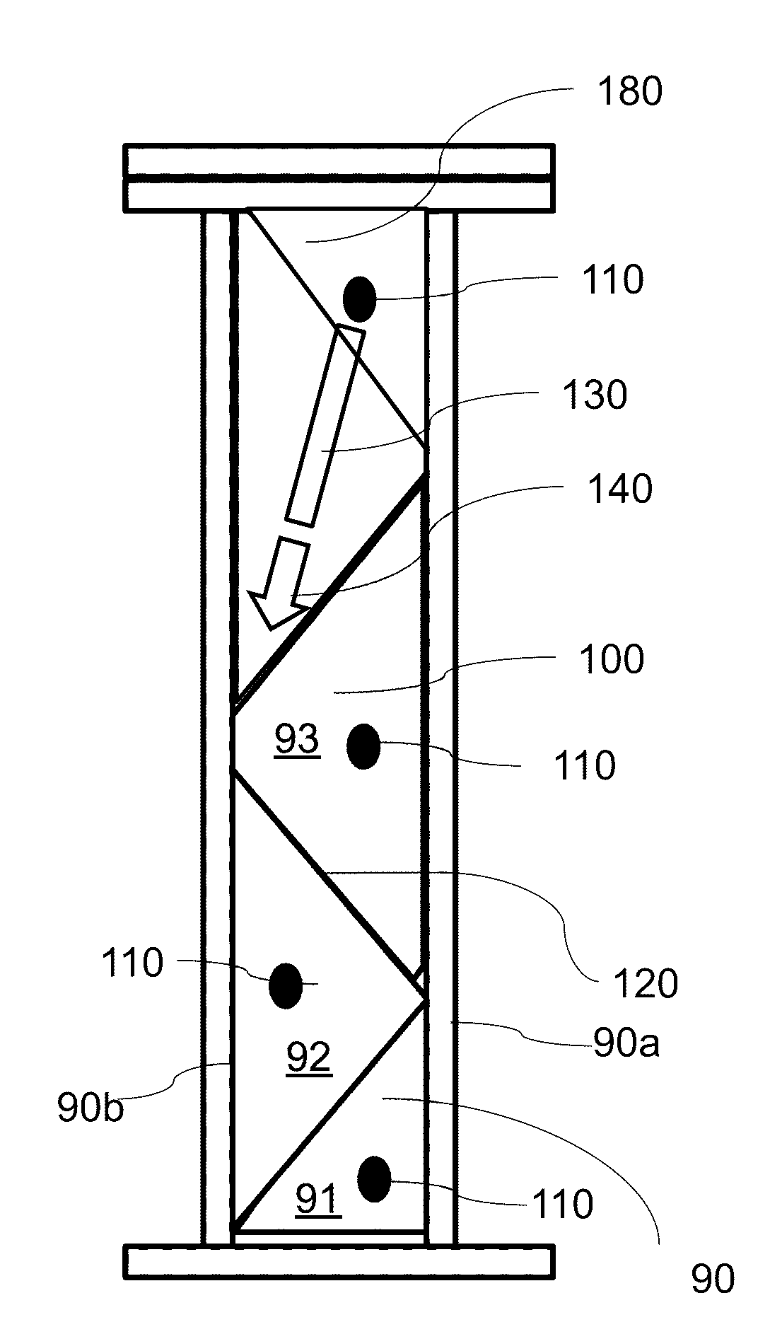
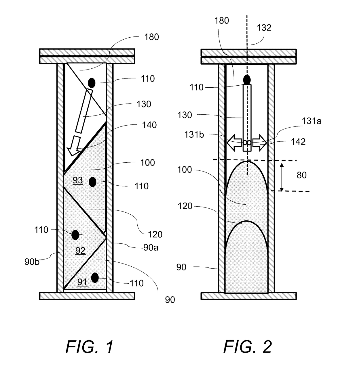
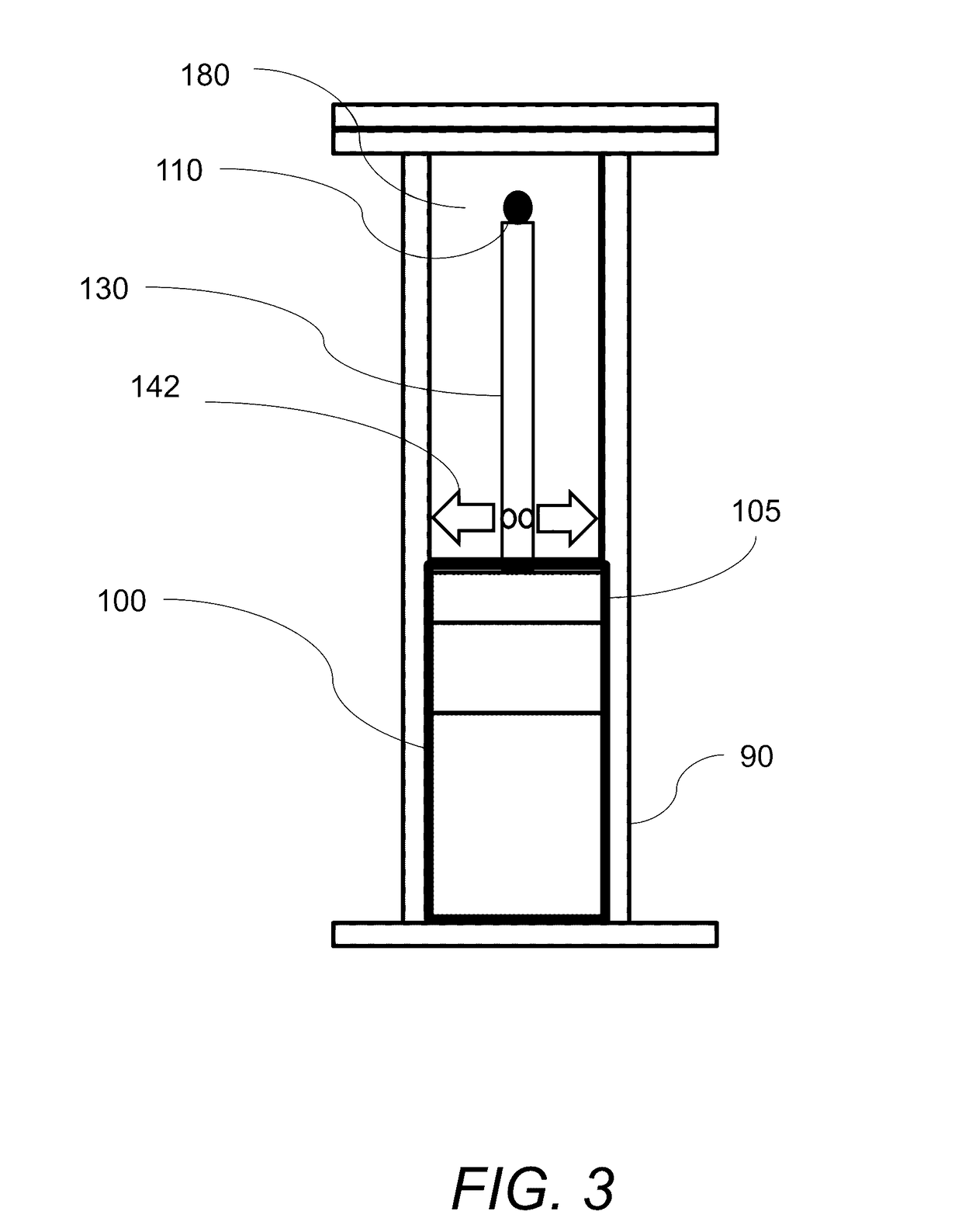
[0110]Foam-in-place insulating foams are formed when an A side chemical (typically isocyanate) and a B side chemical (typically polyol) are mixed to form a mixed partially expanded foam. This mixed partially expanded foam is subsequently sprayed or injected in place where it continues to expand to form a mixed fully expanded foam. Referring to FIG. 1 and FIG. 2, mixed partially expanded foam is injected into a wall cavity 90 either directly through injection holes 110, as shown at the bottom of FIG. 1, or remotely by using a dispense tube 130, as shown at the top of FIG. 2. The mixed partially expanded foam is dispensed either directly from the tip of a dispense gun or by using a short and narrow straw of 6″ or less in length and ½″ or less in diameter attached to the end of the foam gun. The mixed partially expanded foam is injected directly into multiple openings 110 located along the entire interior or exterior surfaces of wall cavity 90. The direct injection of the ...


PUM

PropertyMeasurementUnit
diameteraaaaaaaaaa
payback timeaaaaaaaaaa

Abstract

A method for filling a cavity with an expanding insulating foam component includes the following. First, providing a closed cavity comprising at least one elongated wall surface that extends along a first direction and includes first and second opposite sides, a top side and a bottom side. Next, forming a plurality of openings in the elongated wall surface arranged along the first direction and being alternating close to the first or the second opposite sides. Next, inserting a dispense tube through a first opening of the plurality of openings, and injecting a first portion of the expanding insulating foam into the closed cavity. The first opening is located close to the bottom side and close to the first side of the elongated wall surface. The injected foam expands along the bottom side and the first side and forms a first sloped top surface that has a positive slope angle. Next, inserting the dispense tube through a second opening of the plurality of openings located close and above the first opening and close to the opposite second side, and injecting a second portion of the expanding insulating foam into the closed cavity. The injected foam expands along the first sloped top surface and the second side and forms a second sloped top surface that has a negative slope angle.

Description

CROSS REFERENCE TO RELATED CO-PENDING APPLICATIONS[0001]This application claims the benefit of U.S. provisional application Ser. No. 62 / 222,281 filed on Sep. 23, 2015 and entitled MINIMALLY INVASIVE INJECTION FOAM SYSTEM which is commonly assigned and the contents of which are expressly incorporated herein by reference.FIELD OF INVENTION[0002]The present invention relates to system and a method for a minimally invasive injection foam, and in particular to injection of foam into cavities for retrofit insulation of buildings, insulation of new buildings, insulation of appliances and other articles of manufacture, fabrication of molded preformed foam products and other products containing a two component chemical mixture.BACKGROUND OF THE INVENTION[0003]Heating and cooling of buildings uses approximately 35% of all the energy consumed in the United States of America (USA). Thanks to numerous innovations in construction practices and materials used in new construction, new buildings use...

Claims


Application Information

Patent Timeline
Patent Type & Authority Applications(United States)
IPC IPC(8): B29C44/18E04B1/78E04B1/76B29C44/34B29C44/36
CPCB29C44/18B29C44/3461B29C44/36E04B1/7604E04B1/78B29L2031/10B29K2105/046B29K2105/045B29K2105/12B29K2309/08B29K2067/00B29C44/182B29C44/188B29C44/386B29C44/445B29C67/207B29L2031/776
Inventor LAMM, DOUGLAS
Owner CERTAIN TEED LLC
Why Eureka
Try Eureka