
Coplanar waveguide transition for multi-band impedance matching

a waveguide transition and coplanar waveguide technology, applied in the field of radiofrequency antennas, can solve the problems of significant null of hrn, high cost due to required active electronics, and easy unintentional interference of gps timing antennas at fixed sites, so as to reduce the loss of impedance mismatch, improve the matching characteristics, and reduce the loss of impedance. loss

Active Publication Date: 2017-03-30
MITRE SPORTS INT LTD
View PDF3 Cites 16 Cited by
  • Summary
  • Abstract
  • Description
  • Claims
  • Application Information

AI Technical Summary

Benefits of technology

The patent describes a multi-band stacked microstrip patch antenna with a feed structure that optimizes impedance matching at each layer. This allows for better performance and reduces signal loss compared to conventional antennas. The feed structure can be manufactured using standard printed circuit board methods, making it cost-effective while maintaining good impedance matching.

Problems solved by technology

GPS timing antennas at fixed sites are susceptible to unintentional interference, such as out-of-band and multipath signals, as well as intentional interference from ground-based GPS jammers commonly employed to deny, degrade, and / or deceive GPS derived position and time.
While CRPAs can achieve exceptional nulling in a particular direction, they can be large due to the multiple antenna elements necessary for null steering, are typically expensive due to the required active electronics, and can only null a finite number of interfering signals.
While the HRN's performance is exceptional with regard to its horizon nulling capability, its cost is relatively high due to the required active electronics.
Additionally, the exceptional null of the HRN degrades significantly when installed near other scattering objects, which typically occurs for which happens in most real world installation environments.

Method used


Image

  • Coplanar waveguide transition for multi-band impedance matching
  • Coplanar waveguide transition for multi-band impedance matching
  • Coplanar waveguide transition for multi-band impedance matching

Examples


Embodiment Construction

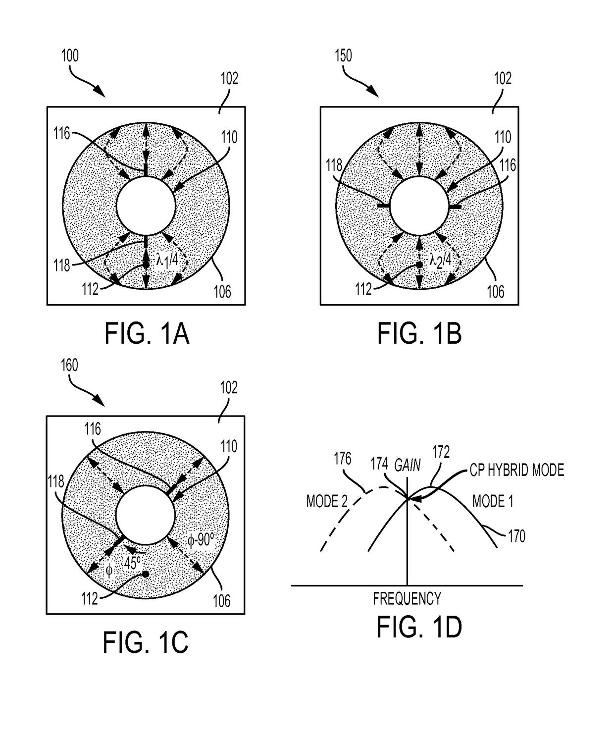
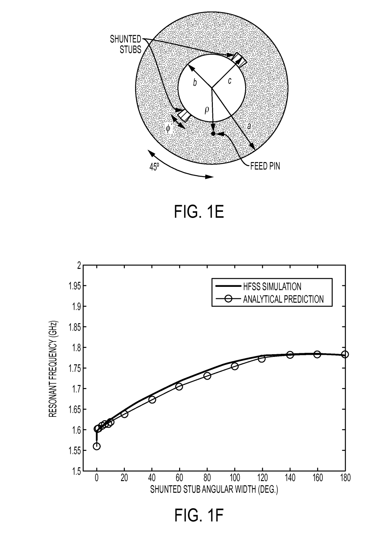
[0042]Described within are SAR microstrip patch antennas that can provide RHCP with only a single feed port. According to some embodiments, a SAR microstrip patch antenna is provided with grounding pathways (shunted stubs) projecting from the inner diameter of the annulus to enable RHCP with just a single feed port spaced 45 degrees from one of the pathways. In some embodiments, antennas include a deep null in the RHCP gain pattern at the horizon in a full ring around azimuth for ground-based interference rejection. These antennas can be configured for dual-band GPS timing reception through stacking of single-mode radiators. Antennas, according to some embodiments, can be made using low-cost PCB architecture. The simplified architecture reduces the number of electronic components necessary to support circular polarization and horizon nulling, thereby reducing the manufacturing cost compared to antennas with similar horizon nulling capability.

[0043]The SAR patch antenna is a well-kno...


PUM


Abstract

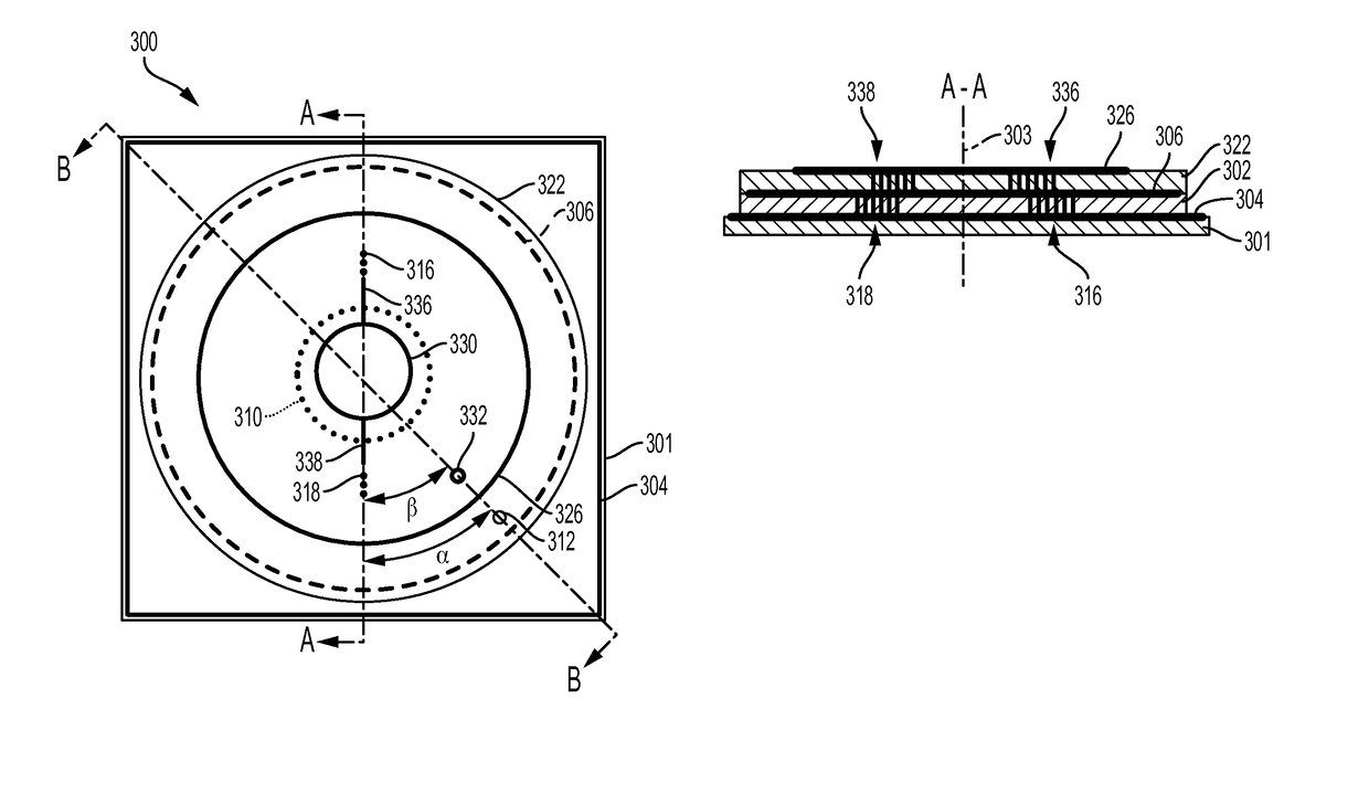
A microstrip antenna including a first substrate, a ground plane disposed on a first side of the first substrate, a first conductive layer disposed on a second side of the first substrate, wherein the first conductive layer is configured to resonate at a first frequency, a second substrate disposed on the first conductive layer, a second conductive layer disposed on a side of the second substrate, wherein the second conductive layer is configured to resonate at a second frequency, a first feed portion extending through the first substrate, and configured to provide first excitation signals to the first conductive layer, a second feed portion extending through the second substrate, wherein the second feed portion is configured to provide second excitation signals to the second conductive layer, and a conductive strip disposed in the first conductive layer and electrically connecting the first feed portion and the second feed portion.

Description

CROSS REFERENCE TO RELATED APPLICATIONS[0001]This application is related to U.S. application Ser. No. ______, titled “SHORTED ANNULAR PATCH ANTENNA WITH SHUNTED STUBS,” filed on Sep. 30, 2015, the entire contents of which are incorporated herein in their entirety.FIELD OF THE INVENTION[0002]This invention relates generally to radio-frequency antennas and, more specifically, to microstrip patch antennas.BACKGROUND OF THE INVENTION[0003]Global Navigation Satellite Systems (GNSS) such as the U.S. NAVSTAR Global Positioning System (GPS), the European Galileo system, the Chinese Beidou system, and the Russian GLONASS system are increasingly relied upon to provide synchronized timing that is both accurate and reliable. (Reference is made to GPS below, by way of example and simplicity, but similar characteristics and principles of operation apply to other GNSS.) GPS antennas are used to receive GPS signals and provide those signals to a GPS receiver. GPS antennas may amplify and filter the...

Claims


Application Information

Patent Timeline
IPC IPC(8): H01Q9/04
CPCH01Q9/0414H01Q9/0435H01Q9/0464H01Q5/40
Inventor MCMICHAEL, IAN T.
Owner MITRE SPORTS INT LTD
Learn More