External-resonator-type light-emitting device

a technology of external resonator and light-emitting device, which is applied in the direction of instruments, semiconductor lasers, optical elements, etc., can solve the problems of difficult to respond to a wide range of temperature changes, limit the improvement of temperature stability of the whole of the external resonator-type light-emitting device, etc., so as to improve the stability of the temperature as a whole device, the effect of enlarging the wavelength region

Active Publication Date: 2017-03-30
NGK INSULATORS LTD
View PDF2 Cites 3 Cited by
  • Summary
  • Abstract
  • Description
  • Claims
  • Application Information

AI Technical Summary

Benefits of technology

[0029]During the course of this study, it is noticed the importance of a combined reflectance, which is obtained by synthesizing the reflectances of Bragg gratings with different periods (pitches). The inventors have then found that the stability on wavelength can be improved, by making the combined reflectance larger than the reflectance at the emitting end of the light source and by providing the wavelength region Δλ50 continuously and in a wide range, provided that the combined reflectance is not less than R50, which is 50% of the maximum value Rmax of the combined reflectance in the wavelength region Δλ50. The inventors thus reached the idea of enlarging the wavelength region.
[0030]The oscillation of laser from an external resonator type light emitting device by the Bragg grating takes place, where the gain of light returning into the light source after reflected by the Bragg grating is larger than the gain of the light returning into the light source after reflected at the emitting end of the light source, at a wavelength exceeding the oscillation threshold value. Then, when the environmental temperature is changed, the wavelength of laser light oscillating from the light source is shifted. At this time, the wavelength region Δλ50 is made continuous in a wide range, provided that the combined reflectance of the Bragg gratings is not less than 50 percent R50 of the maximum value Rmax in the wavelength region Δλ50. As a result, when the peak wavelength of the gain of the light source is shifted, responsive to the shift, the Bragg gratings function as a whole so that the gain of light reflected by the Bragg gratings constantly exceeds the gain of light reflected at the emitting end of the light source. The laser oscillation of the external resonator type can be thus made possible. The stability on the temperature as whole device can be considerably improved, and attained the present invention.

Problems solved by technology

However, in actuality, there is a limit on the improvement of temperature stability of the whole of the external resonator type light emitting device, and it may be required a mechanism of temperature control such as a Peltier device in many cases.
Particularly, it is difficult to respond to a wide range of temperature change by means of an external resonator type light emitting device.

Method used


Image

  • External-resonator-type light-emitting device
  • External-resonator-type light-emitting device
  • External-resonator-type light-emitting device

Examples


example 1

[0162]The external resonator type laser module was prepared as shown in FIG. 6. The light-emitting device as shown in FIGS. 4 and 15(b) was produced.

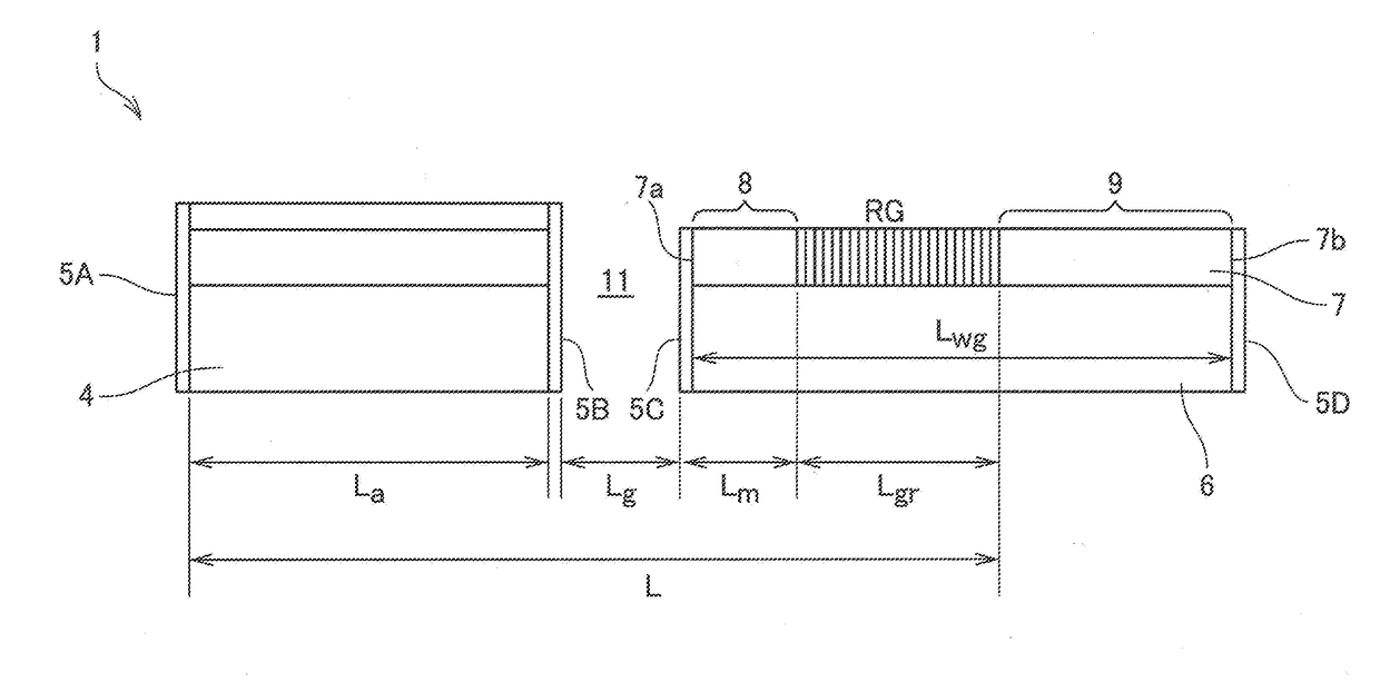
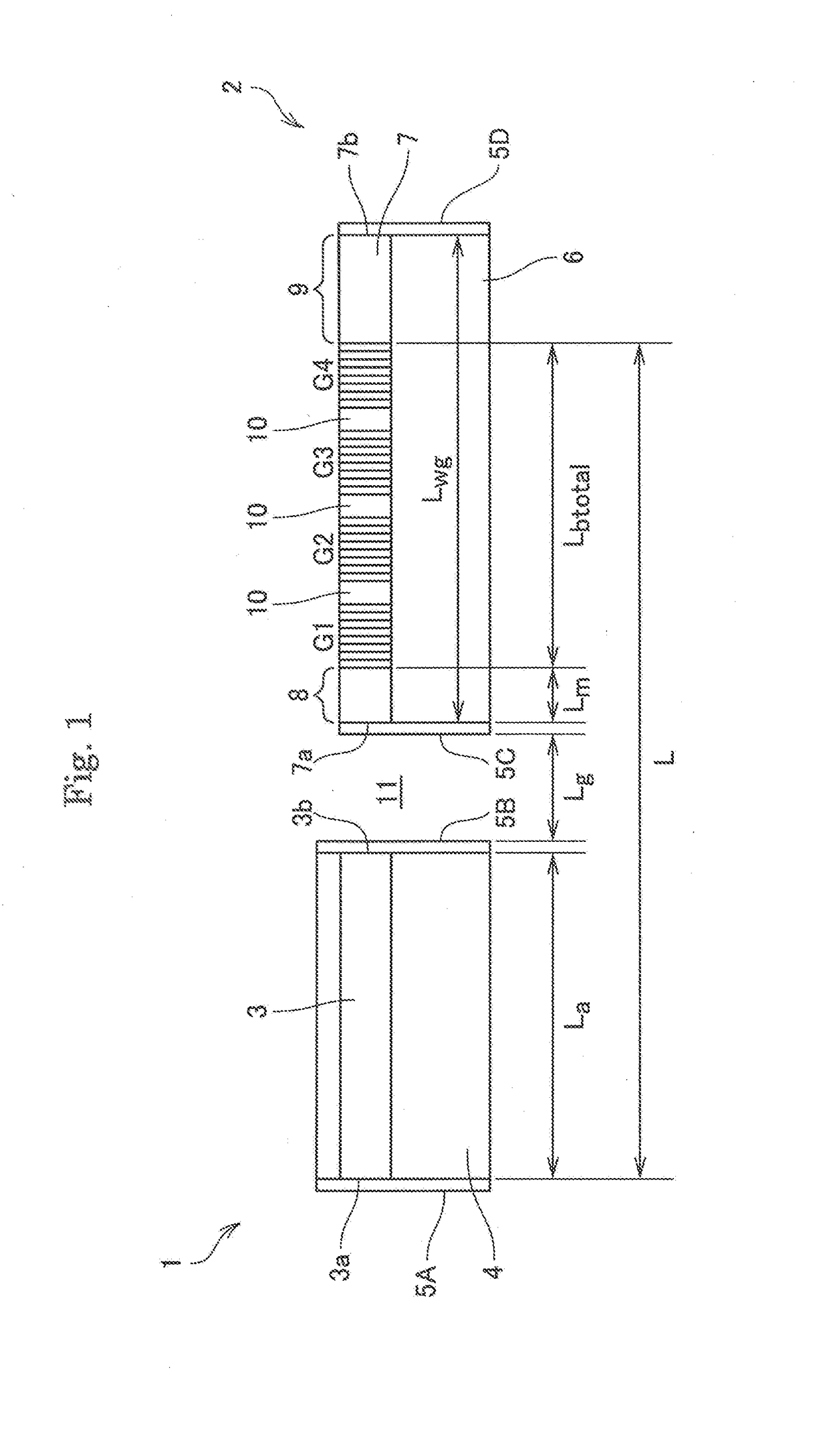
[0163]Specifically, a 1 μm thick SiO2 layer as a lower side buffer layer 13 was formed on a supporting substrate 6 formed from quartz by a sputtering apparatus, and a 1.2 μm thick Ta2O5 film was formed thereon to form an optical material layer 30. Next, Ti was film-formed on the optical material layer to prepare grating patterns with an EB lithography apparatus. Then, Ti patterns were used as a mask, and three Bragg gratings G1, G2 and G3 were formed by fluorine-based reactive ion etching. The length of the intermediate propagating portion 10 was 0 μm. The grating groove was set to have a depth td of 200 nm.

G1: Pitch interval Λ 190 nm, length Lb 8 μm

G2: Pitch interval Λ 192.5 nm, length Lb 8 μm

G3: Pitch interval Λ 195 nm, length Lb 8 μm

[0164]Further, in order to form an optical waveguide, reactive ion etching was carried out by the same...

example 2

[0187]The light-emitting device similar to that of the example 1 was produced.

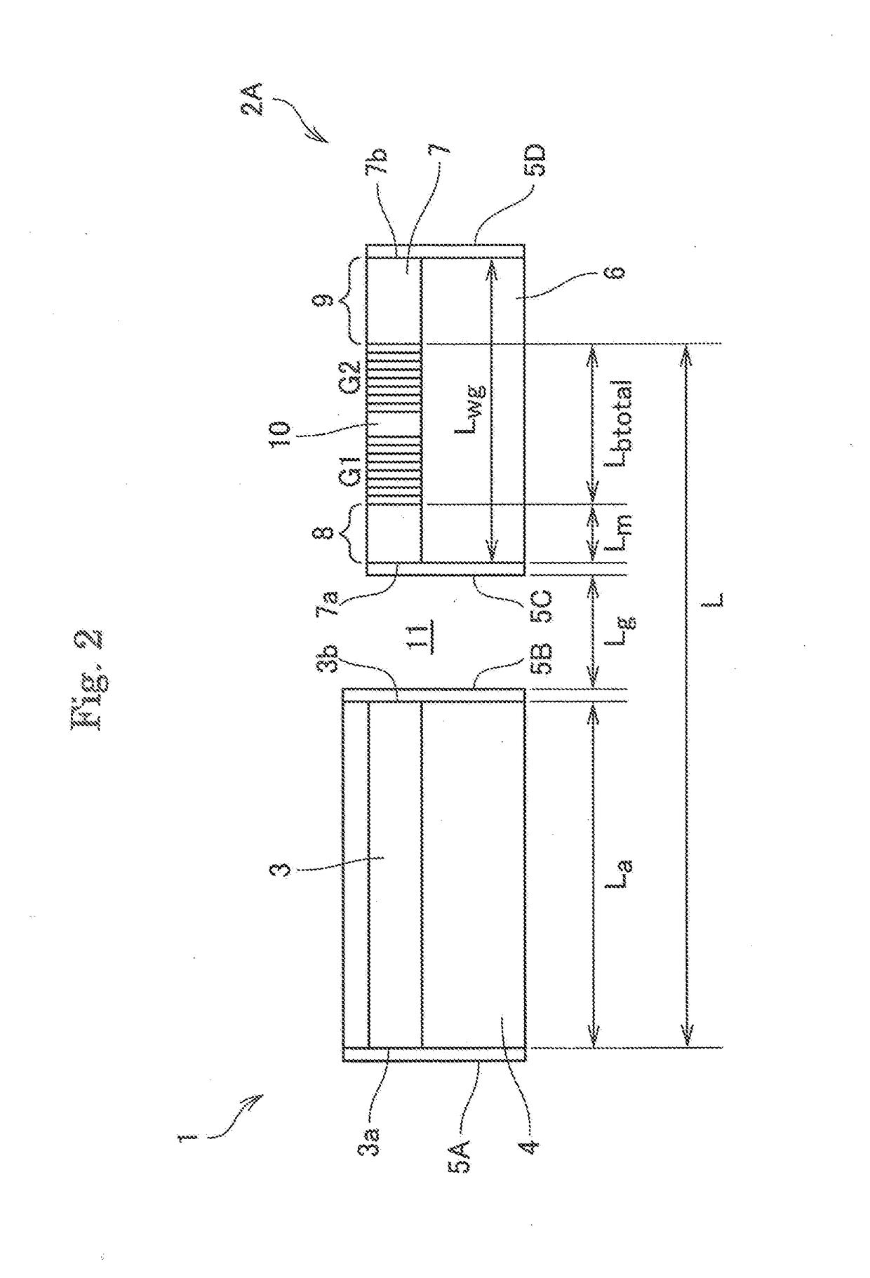
[0188]However, in the grating device, it was formed the following gratings G1 and G2 (refer to FIG. 5). The grating groove was set to have a depth td of 200 nm.

G1=Pitch interval Λ 191 nm, length Lb 6 μm

G2=Pitch interval Λ 193 nm, length Lb 6 μm

[0189]As to optical characteristics of the grating element, a super luminescence diode (SLD) as a wide band wavelength light source was used, and output light was analyzed with an optical spectrum analyzer by inputting light in the TE mode to the grating element to evaluate reflection characteristics from the transmission characteristics.

[0190]The reflection central wavelength of measured grating element was 791 nm, its maximum reflectance was 30%.

[0191]Next, in order to evaluate characteristics of the external resonator type laser in which this grating element was used, the laser module was mounted as shown in FIGS. 6 and 19. As a light source element, a GaAs system...


PUM


Abstract

An external resonator type light-emitting device includes a light source oscillating a semiconductor laser light and a grating element configuring an external resonator together with the light source. The light source includes an active layer oscillating said semiconductor laser light. The grating element includes an optical waveguide and a plurality of Bragg gratings formed in the optical waveguide. The optical waveguide includes an incident face to which the semiconductor laser light is incident and an emitting face from which an emitting light having a desired wavelength is emitted. A half value reflectance R50 is larger than a reflectance R2 at an emitting end of the light source. A half value reflectance R50 is 3% or larger. A combined reflectance is not less than the half value reflectance R50 in a wavelength region Δλ50. The wavelength region Δλ50 is continuous over 10 nm or more and 30 nm or less, provided that a half value reflectance is defined as 50 percent of a maximum value Rmax of the combined reflectance of the Bragg gratings.

Description

TECHNICAL FIELD[0001]The present invention relates to an external resonator type light-emitting device.BACKGROUND ARTS[0002]According to a DBR laser, concave and convex portions are formed on the surface of a waveguide extended from the waveguide of the active layer to configure a mirror by utilizing Bragg reflection for realizing a resonator. Since diffraction gratings are provided on both ends of an optical waveguide layer according to this laser, light emitted from the active layer is propagated through the optical waveguide layer; a part of the propagating light is reflected by the diffraction gratings and returned into a current injection part; and then amplified. As light having only a specific wavelength is reflected in the determined direction from the diffraction grating, the wavelength of the laser light is made constant.[0003]According to a DBR laser formed monolithically in a semiconductor substrate, gratings are formed on an extension of the waveguide of the active laye...

Claims


Application Information

Patent Timeline
Patent Type & Authority Applications(United States)
IPC IPC(8): H01S5/14
CPCH01S5/146H01S5/141G02B6/1228G02B6/124G02B6/13G02B6/29359H01S5/1215H01S5/14H01S5/10H01S5/1003H01S5/1014H01S5/1025H01S5/1237
Inventor KONDO, JUNGOYAMAGUCHI, SHOICHIROEJIRI, TETSUYA
Owner NGK INSULATORS LTD
Why Eureka
Try Eureka