

Polymer electrolyte membrane, and membrane-electrode assembly and fuel cell containing same
a technology of electrolyte membrane and membrane electrode, which is applied in the direction of fuel cells, electrochemical generators, non-aqueous electrolytes, etc., can solve the problems of increased ohmic loss, increased use of expensive materials, and thus deterioration of energy conversion efficiency, so as to maximize the functions of an ionic conductive group and enhance the operation function of the fuel cell. , the effect of improving the resistance to radical attacks
- Summary
- Abstract
- Description
- Claims
- Application Information
AI Technical Summary
Benefits of technology
Problems solved by technology
Method used
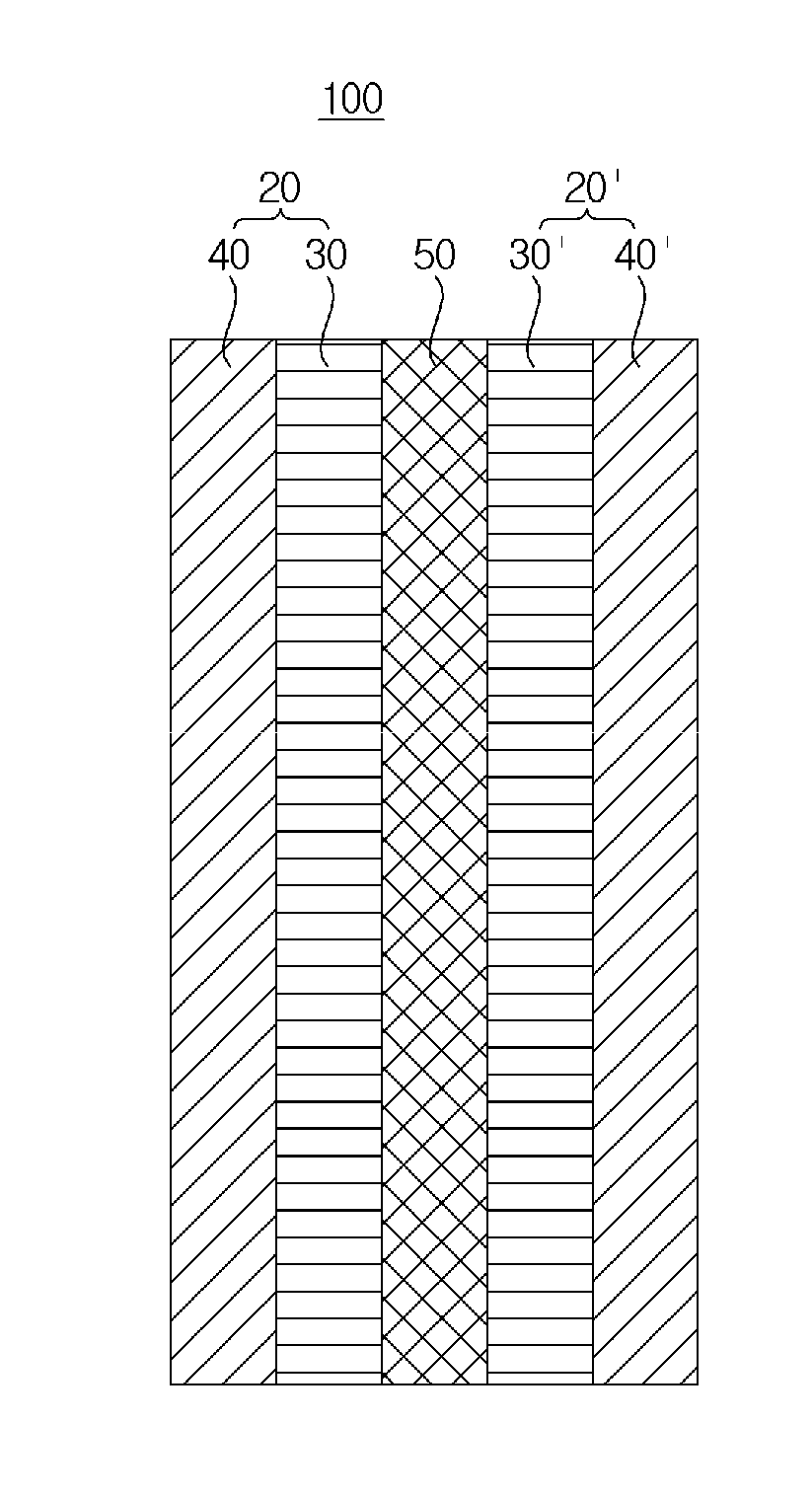
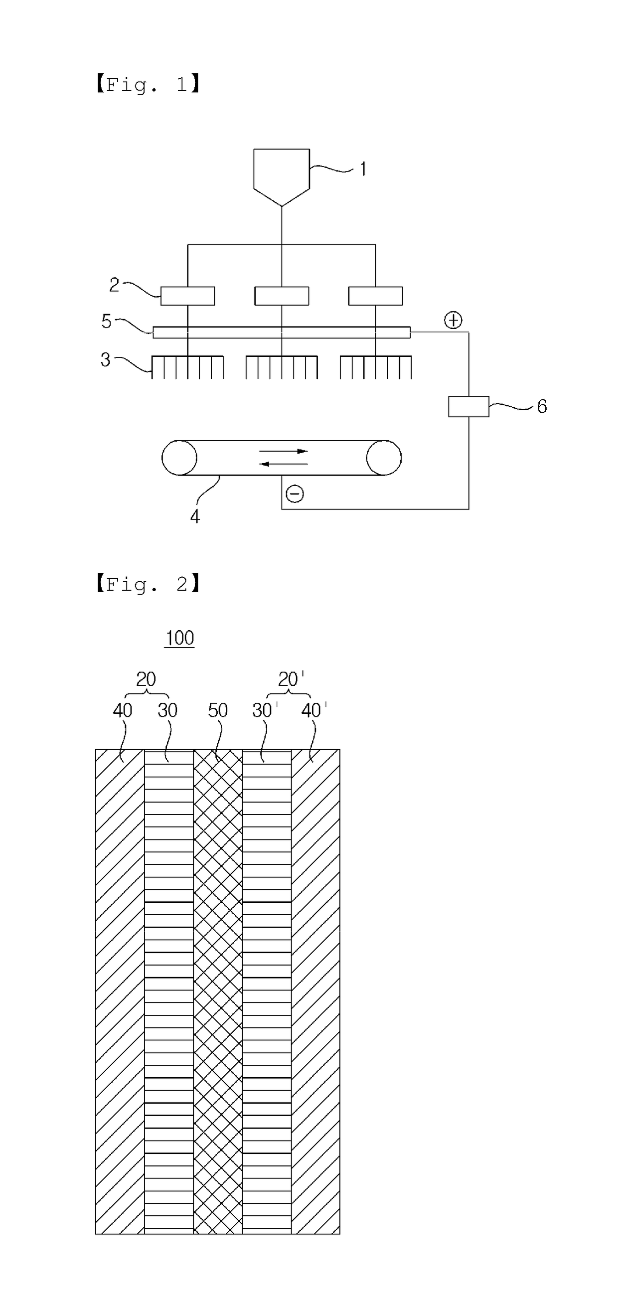
Image

Examples
preparation example 1
r
Comparative Example 1-1
[0135]After a 4-neck round flask and a Dean-stark trap were installed, 4,4′-biphenol (BP, in an amount of 100 parts by mole with respect to 50 parts by mole of SDCDPS described below) and K2CO3 were added to NMP and toluene, and the resulting mixture was stirred in a mechanical stirrer and the temperature was slowly elevated to 150° C. for about two hours. The reaction solution was refluxed in toluene through the dean-stark trap for about 4 hours at the temperature of 150° C. and toluene was then removed. The dried 3,3′-disulfonated-4,4′-dichlorodiphenyl sulfone (SDCDS) and 4,4′-dichlorodiphenyl sulfone (DCDPS) were weighed in a molar ratio of 50:50 in a glove box and then added together with NMP to a reactor. After the temperature was slowly elevated to 195° C., stirring was conducted for 16 hours. After completion of polymerization, the resulting product was precipitated in water to remove the salt at 100° C. for 2 hours, followed by filtering. The resultin...
example 1-1
[0136]After a 4-neck round flask and a dean-stark trap were installed, dihydroxy bipyridine (in an amount of 100 parts by mole with respect to 50 parts by mole of SDCDS described below) and K2CO3 were added to N-methyl-2-pyrrolidone (NMP) and toluene, and the resulting mixture was stirred in a mechanical stirrer and the temperature was slowly elevated to 150° C. for about two hours. The reaction solution was refluxed in toluene through the dean-stark trap for about 4 hours at the temperature of 150° C. and toluene was then removed. The dried SDCDS and DCDPS were weighed in a molar ratio of 50:50 in a glove box and then added together with NMP to a reactor. After the temperature was slowly elevated to 195° C., stirring was conducted for 16 hours. After completion of polymerization, the resulting product was precipitated in water to remove the salt at 100° C. for 2 hours, followed by filtering. The resulting filtrate was dried to obtain the polymer.
preparation example 2
r Electrolyte Membrane
PUM
| Property | Measurement | Unit |
|---|---|---|
| humidity | aaaaa | aaaaa |
| humidity | aaaaa | aaaaa |
| thickness | aaaaa | aaaaa |
Abstract
Description
Claims
Application Information