Coated stacks for batteries and related manufacturing methods

a technology of coating stacks and batteries, applied in the direction of batteries, sustainable manufacturing/processing, cell components, etc., can solve the problems of complex and expensive equipment, inefficient and costly construction and operation, and the existing process of manufacturing lithium batteries, etc., to achieve less complex, less expensive, and higher speed

Pending Publication Date: 2017-04-06
META MATERIALS INC
View PDF9 Cites 36 Cited by
  • Summary
  • Abstract
  • Description
  • Claims
  • Application Information

AI Technical Summary

Benefits of technology

[0009]It is an object of the present invention to provide a battery stack or battery that could be fabricated on less complex, less expensive and higher speed automated processing equipment than, for example, the equipment utilized for portable computer batteries, and furthermore is particularly adapted for making flat, such as prismatic or pouch, batteries. It is another object to provide a battery that comprises separator and metal layers that are thinner than those currently used. It is another object of the present invention to enable the battery to contain a greater content of electroactive material so as to provide more capacity. Another object is to make batteries safer by reducing the potential for manufacturing defects and including active safety features in the battery, such as a shutdown layer, and separator layers that are self-healing of tears and holes. Another object is provide a battery that is less expensive to make than existing batteries.

Problems solved by technology

Existing processes for manufacturing lithium batteries, including rechargeable and non-rechargeable lithium batteries, and other types of batteries, are relatively slow, complex and expensive.
To maintain the alignment of the strips of these materials and for other quality reasons, this interleaving is usually done on manufacturing equipment that is inefficient and costly to construct and operate.
In addition, known lithium batteries have limited energy density and power density.
Among other reasons, this is because the separators and the conductive metal substrates in these known batteries are relatively thick, thereby limiting the volume of electroactive material that is present in the battery.
However, these materials are not electrochemically active and, thus, lower the volume of the electroactive or electrochemically active material that is present in current lithium batteries and therefore provide less than ideal capacity.
This has been known to result in metal fragments being embedded into the separator or other portion of the finished battery, which can lead to a short circuit, or other dangerous condition.

Method used


Image

  • Coated stacks for batteries and related manufacturing methods
  • Coated stacks for batteries and related manufacturing methods
  • Coated stacks for batteries and related manufacturing methods

Examples


Embodiment Construction

[0029]This invention pertains to coated battery stacks for use in batteries, such as lithium ion batteries and lithium metal batteries, as well as methods of making such batteries and related coated battery stacks. The coated battery stacks and batteries of the present invention have a lower cost, improved power and energy densities, and improved safety.

[0030]The present invention includes, but is not limited to, the following designs for lithium batteries and coated stacks and methods of making such batteries and coated stacks. In the following examples, the coated stack may be either an anode stack or a cathode stack, depending on the electrode material selected.

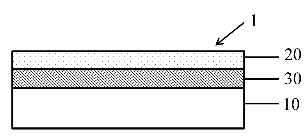
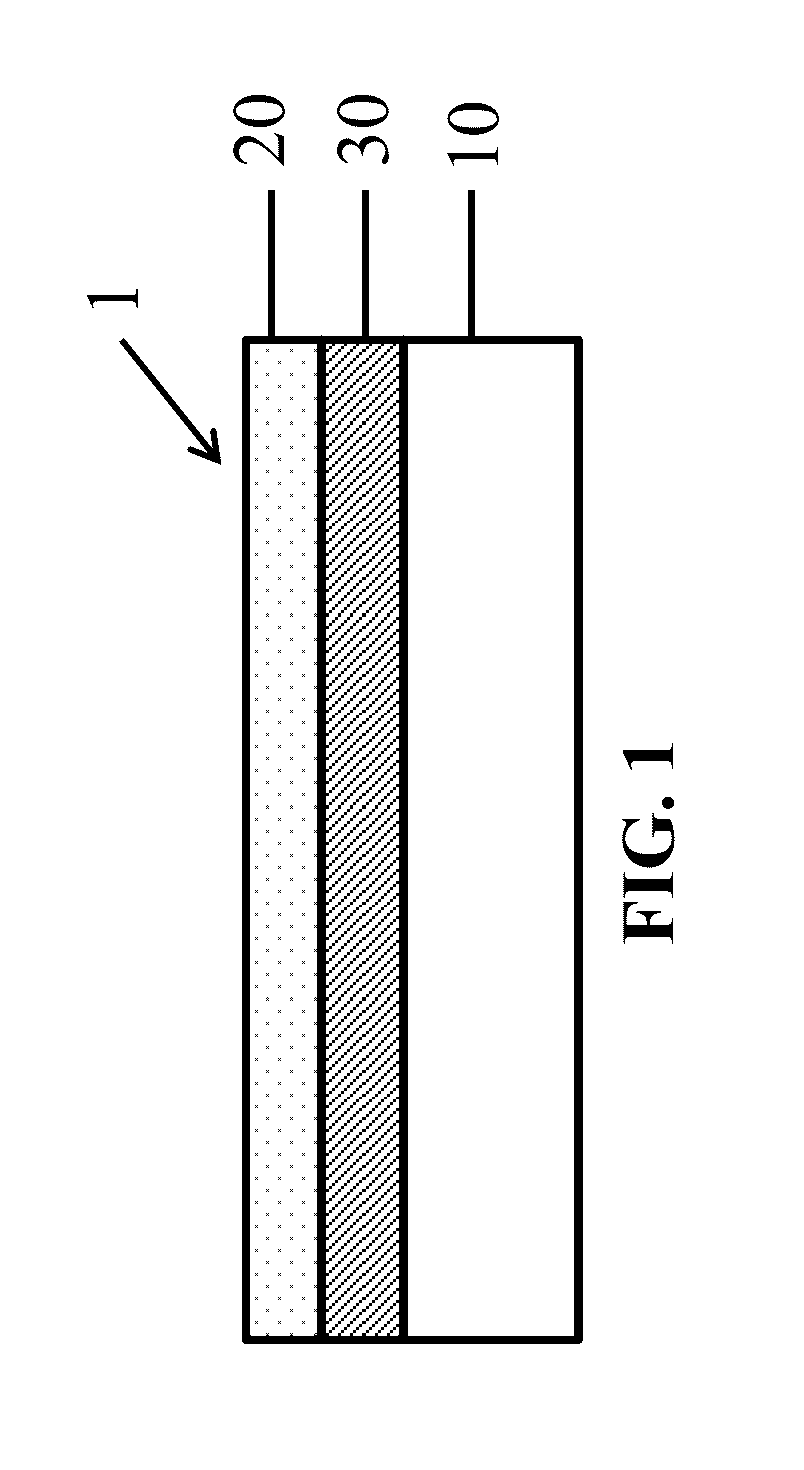
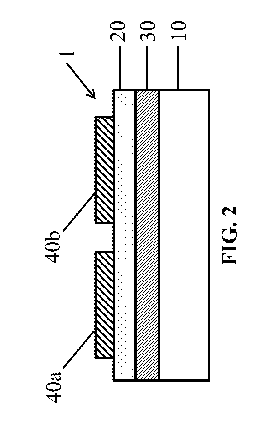
[0031]One aspect of the present invention will be described with reference to a process for manufacturing a lithium battery. As described in greater detail below, the process utilizes a reusable substrate 10, onto which the various layers of the battery stack are coated. Once the battery stack is assembled, the battery lay...


PUM

PropertyMeasurementUnit
thickaaaaaaaaaa
pore sizeaaaaaaaaaa
thicknessesaaaaaaaaaa

Abstract

Provided is a battery stack for use in an electric current producing cell, wherein the coated stack comprises a porous separator, an electrode layer adjacent the porous separator, and a current collector layer coated on the electrode layer, wherein the current collector layer comprises sintered metal particles. Also provided are methods of manufacturing such coated stacks.

Description

RELATED APPLICATIONS[0001]This application claims the benefit of and priority to U.S. Provisional Patent Application No. 62 / 178,633, filed Apr. 15, 2015, and U.S. Provisional Patent Application No. 62 / 231,539, filed Jul. 9, 2015, the contents of which are incorporated herein by reference in their entirety.STATEMENT OF GOVERNMENT RIGHTS[0002]This invention was made with government support under Grant Number DE-EE00054333 awarded by the U.S. Department of Energy. The government has certain rights in the invention.FIELD OF THE INVENTION[0003]The present invention generally relates to the field of batteries and other electric current producing cells, such as capacitors and lithium-ion capacitors. More particularly, the present invention pertains to coated stacks for lithium and other types of batteries, such as sodium and magnesium batteries, where the various layers of the battery, including the electrode and current collector, are coated on a porous separator and to methods of prepari...

Claims


Application Information

Patent Timeline
Patent Type & Authority Applications(United States)
IPC IPC(8): H01M10/058H01M10/0525H01M2/14H01M4/66H01M2/16H01M50/403H01M50/414H01M50/431H01M50/434H01M50/449H01M50/451H01M50/489
CPCH01M10/058H01M4/661H01M2/1646H01M2/1653H01M2/1686H01M2220/30H01M10/0525H01M2004/027H01M2004/028H01M2220/20H01M2/145H01M50/431H01M50/46H01M50/446H01M50/449H01M10/4235H01G11/50H01G11/52B82Y40/00H01M4/0407H01M10/052H01M10/0587Y02E60/10H01M50/403Y02P70/50H01M50/451H01M50/414H01M50/434H01M50/489H01M4/505H01M4/525H01M4/5825Y02T10/70
Inventor CARLSON, STEVEN A.SLOAN, BENJAMINAVISON, DAVID W.
Owner META MATERIALS INC
Why Eureka
Try Eureka