Antenna mandrel with multiple antennas

a mandrel and antenna technology, applied in the field of ophthalmic devices, can solve the problems of excessive electromagnetic field exposure, high voltage on the electrodes required to transmit significant power, and becoming increasingly more likely to create wearable or embeddable microelectronic devices, etc., and achieve the effect of quick and convenien

Active Publication Date: 2017-04-27
JOHNSON & JOHNSON VISION CARE INC
View PDF2 Cites 17 Cited by
  • Summary
  • Abstract
  • Description
  • Claims
  • Application Information

AI Technical Summary

Benefits of technology

[0013]The present invention relates to a device that enables communication between an ophthalmic lens assembly containing a radiation element and a physical object. The device may be utilized to enable radio frequency for reading and programming data, serial number identification, power transfer, tracking and management. More specifically the present invention relates to methods and means of wirelessly connecting internal antenna arrangements in ophthalmic devices to external radiation elements so as to propagate their radio waves. The device preferably provides a quick and convenient method to couple electromagnetic energy from circuit elements with built-in antennas embedded in an ophthalmic lens, for example, a contact lens so that it may be used as a mechanism for collecting medical data, transmitting information or data to a medical administrator or manufacturer for assessment, or more generally speaking a method for utilizing near field communication technologies.
[0019]Due to the miniaturization of the components the expected range of k is 0≦k≦0.002, however k may be maximized utilizing the following relationship,k≤(rsmallrlarge)2,(1)where rsmall and rlarge represent the radii of the antenna coils, and the upper bound for k is based on the area ratio for two co-planar spiral conductors aligned about their center. Additionally, the limited space within an ophthalmic device restricts both radii from exceeding submillimeter-sized ranges to maximize the coupling coefficient. Therefore, a relatively small misalignment of the coils causes the coupling coefficient to change. Even a 0.2 mm misalignment of the coils could then result in insufficient power to the secondary coil because more of the magnetic field from the first coil misses the second coil. Higher efficiencies may be achieved if the coils are closer together, and the coils' axes are aligned. To overcome this limitation and enable higher power transfer, the present invention mimics the shape of the lens structure so that the antennas are closer together and the coils' axes may be easily coarse-aligned. The antennas occupy an area of approximately 40 square millimeters. This area has an inner diameter of 7 millimeters and an outer diameter of 10 millimeters, and is configured to interface with an antenna on the concave or convex side of the lens. Geometrically matching the antenna structure to the lens, and concentrating the antennas on the substrate within the aforementioned area, may reduce the complexity of trying to coarse-align micron-sized antennas to initiate coupling. The antenna mandrel may be coarse-aligned with the lens structure, so that multiple antennas on the mandrel may be positioned closely to the same region as the antenna embedded in the ophthalmic device. In some embodiments, the present invention may comprise a robotic vision system to facilitate and expedite the coarse-alignment and the fine-tune alignment process. For example, the robotic vision system may be configured to move or rotate about one or more of the planes in three-dimensional space, in order to locate the submillimeter-sized antenna embedded in the ophthalmic device. In another embodiment, the robotic vision system may be fixed and connected to a moveable base that rotates or moves about one or more planes in three-dimensional space to allow a vision system to fully scan the ophthalmic device for the submillimeter-sized antenna. Once the antennas have been coarse aligned, fine-tuning or final alignment may be quickly completed by making small adjustments to the orientation of the mandrel via electrical or mechanical movements or rotations about one or more planes in three-dimensional space. Electronically interrogating the matrix of antennas on the antenna mandrel through a controller and / or the ability search the ophthalmic device for the submillimeter-sized antenna may expedite the communication process.

Problems solved by technology

As electronic devices continue to be miniaturized, it is becoming increasingly more likely to create wearable or embeddable microelectronic devices for a variety of uses.
Capacitive coupling is not traditionally used in low-power applications such as the present invention because the high voltages on the electrodes required to transmit significant power may potentially be hazardous.
Additionally, electric fields interact strongly with most materials, including the human body, and may possibly cause excessive electromagnetic field exposure.
Embedding electronics and communication capabilities in a contact lens presents a number of general challenges.
In general, it is difficult to manufacture such components directly on the lens for a number of reasons, as well as mounting and interconnecting planar devices on a non-planar surface.
It is also difficult to manufacture to scale.
It may also difficult to make a contact lens comfortable and safe for the wearer with the added thickness of additional components.
With respect to communication devices, specific challenges include limited antenna efficiency, which is directly related to the size or area for a coil antenna, and the number of coil turns.
Although, the limit of miniaturization of electronic devices has yet to be determined, the sizes of some elements in electronics remain constrained by the rules of physics, and cannot match the miniaturization demonstrated by circuit elements.
The size of the antenna relates to the maximum inductance achievable and the maximum voltage or current that may be transferred to the device, and differential sizing has the potential to delay or exacerbate the ability to coarse-align and fine-tune align antennas to initiate a communication link.
The primary issue is that, if any antenna is small enough to include on a circuit embedded in an ophthalmic device, it may not provide sufficient power levels.
In some cases it may not be desirable to simply increase the power applied to the external antenna or to alter the size or number of turns.
A larger size ratio between the two antennas could result in non-predictable or performance-degrading characteristics.
However, considering the fundamental size constraints of the internal antenna, equally sized antennas would cause the antenna coils to be extremely sensitive to alignment.
Even the slightest mis-alignment of the coils may result in insufficient power.
Moreover, this difficulty increases greatly when utilizing micron-sized antennas, where one antenna is embedded inside an ophthalmic device, which eliminates the possibility of any direct contact coupling methods.

Method used


Image

  • Antenna mandrel with multiple antennas
  • Antenna mandrel with multiple antennas
  • Antenna mandrel with multiple antennas

Examples


Embodiment Construction

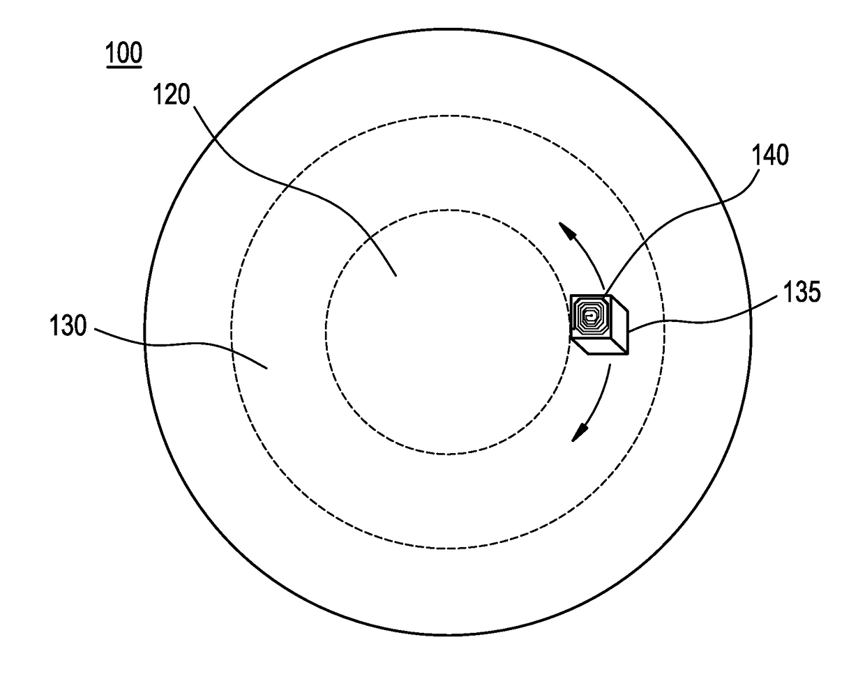
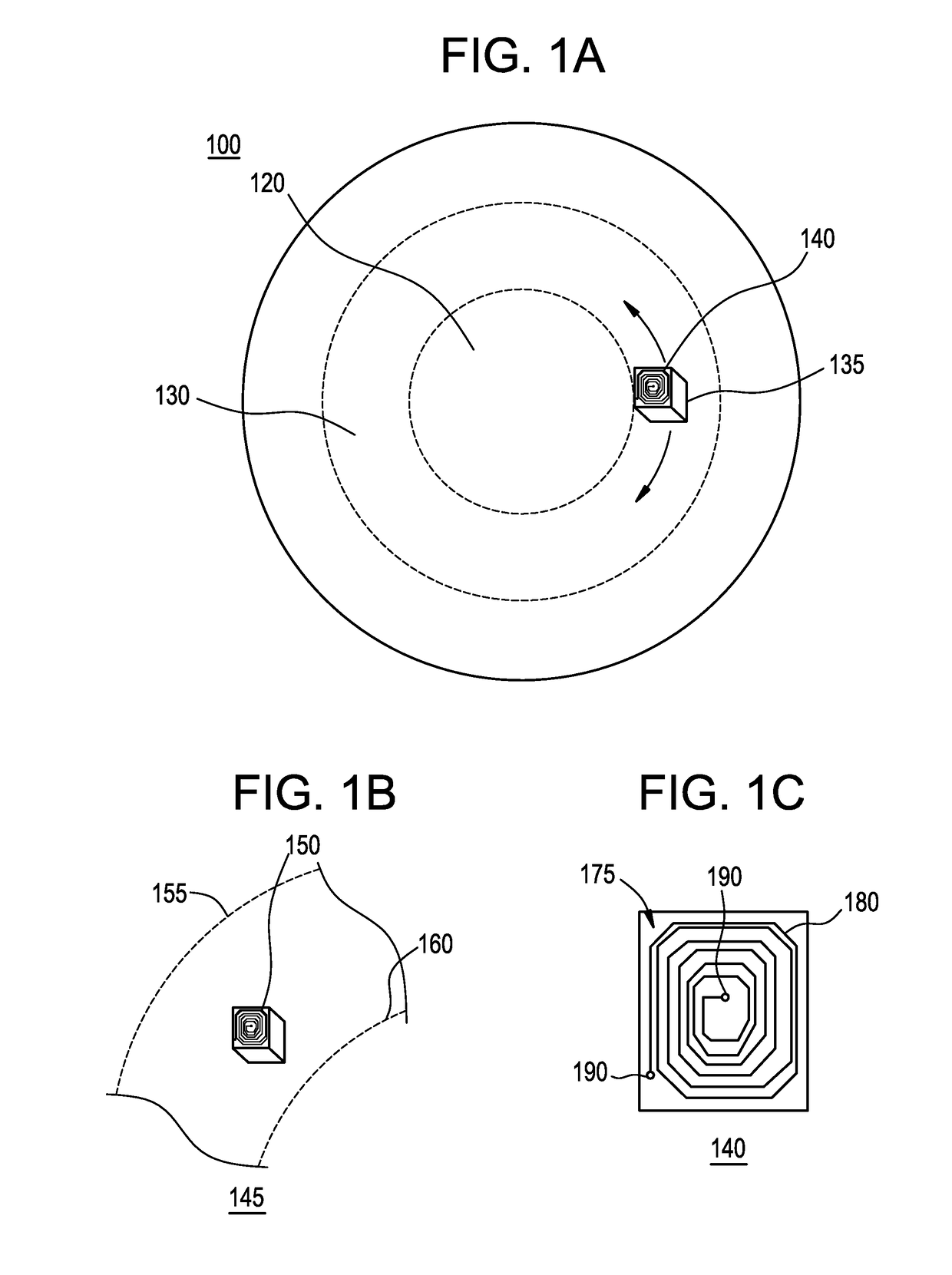
[0033]Referring to FIG. 1A, there is illustrated a first exemplary embodiment of an ophthalmic device 100. Although illustrated as a contact lens, it is important to note that the present invention may be utilized in conjunction with any number of devices having medical and ophthalmic applications as well as any devices incorporating lenses, such as cameras, binoculars and microscopes. The exemplary ophthalmic device 100 comprises a circuit element 135 with built-in submillimeter-sized antenna 140 positioned outside of the optic zone 120 in the peripheral zone 130. As utilized herein, the circuit element 135 may comprise one or more electric components embedded on any suitable substrate, including copper traces on a polyimide, aluminum or copper on silicon oxide or silicon nitride, or other conductors on insulators. Circuit element 135 may be configured with the necessary electrical components to execute any number of applications for the ophthalmic device. The antenna 140 may be fo...


PUM


Abstract

Antennas and antenna mandrels or assemblies may be designed and configured to enable one of one- or two-way communication and / or power transfer with mechanical devices such as ophthalmic devices, including contact lenses. These antennas and antenna mandrels or assemblies may be utilized to transmit data from the mechanical devices to receive data from a transmitter, and / or inductively charge an electromechanical cell or the like incorporated into a mechanical device.

Description

BACKGROUND OF THE INVENTION[0001]1. Field of the Invention[0002]The present invention relates to a device that includes an array of small antennas on a mandrel capable of interfacing with biomedical devices, and more particularly ophthalmic devices, such as wearable lenses, including contact lenses, implantable lenses, including intraocular lenses (IOLs) and any other type of device comprising optical components that incorporate electronic circuits and associated antennas / antenna assemblies to enable one of one- or two-way communication with the one or more electronic components and / or power transfer.[0003]2. Discussion of the Related Art[0004]As electronic devices continue to be miniaturized, it is becoming increasingly more likely to create wearable or embeddable microelectronic devices for a variety of uses. Such uses include monitoring aspects of body chemistry, administering controlled dosages of medications or therapeutic agents via various mechanisms, including automatically,...

Claims


Application Information

Patent Timeline
Patent Type & Authority Applications(United States)
IPC IPC(8): G02C11/00H01Q3/00G02C7/04A61F2/16H01Q7/00H01Q21/06
CPCG02C11/10H01Q7/00H01Q3/005G02C7/049A61F2/16H01Q21/061H01Q1/2225H01Q21/0025H01Q1/22H01Q1/38H01Q21/00G02C7/04H04B5/00A61F2250/0001A61F2250/0002H01Q15/02H01Q15/16H01Q19/06H01Q1/2208
Inventor BEATON, STEPHEN R.FERRAN, MICHAEL D.OWENS, DAWN JAMISHAPUGH, RANDALL B.TONER, ADAM
Owner JOHNSON & JOHNSON VISION CARE INC
Why Eureka
Try Eureka