Spray System for Dust Control on a Mining Machine

a mining machine and dust control technology, applied in the direction of dust removal, slitting machines, separation processes, etc., can solve the problems of reducing dust standards, affecting and affecting the dust control of mines, so as to improve the wetting of generated dust and minimize the escape of dust. , the effect of improving the wetting

Inactive Publication Date: 2017-05-04
SOUTHERN ILLINOIS UNIVERSITY
View PDF0 Cites 15 Cited by
  • Summary
  • Abstract
  • Description
  • Claims
  • Application Information

AI Technical Summary

Benefits of technology

[0014]The above mentioned needs are solved by the present invention. Several concepts were developed and implemented in the present invention for improving the dust control using hydraulic sprays on longwall shearers. These concepts include in combination or in parts utilizing several approaches that include: 1) Improving wetting of generated dust at the source, 2) Minimizing escape of the dust from the generation areas toward the areas where intake air can entrain it and travel toward the mine worker locations; 3) Providing mine worker locations a relatively un-contaminated air stream; 4) Creating hydraulic curtains to create barriers to airflow and to modify air circulation patterns so that mine workers are not exposed to high concentration dust-laden air. As such, various embodiments are presented that improve the dust control with a modified spray system from what has been traditionally employed.

Problems solved by technology

Increased production rates and high out-of-coal seam dilution (over 25%) in the United States and around the globe continue to generate dust control problems in mining areas.
The National Institute for Occupational Safety and Health (NIOSH) recognizes this disease as being severely disabling, potentially lethal, and entirely preventable through respirable (less than 10 micron) dust control.
Additionally, several mines face reduced dust standards due to high respirable quartz content in the dust.
The shearer operators (SOs), roof support operators (ROs), and maintenance workers are likely to be overexposed to respirable dust.
Dust control is a very important research problem in the USA and around the globe to meet the current US regulatory coal dust exposure requirement of 2 mg / m3 averaged over an 8-hour period.
This problem has become even more critical with the implementation of new dust control regulations effective Aug. 1, 2014.
It is unanimously accepted among the professionals that meeting these requirements around the face area in longwall coal mines will be an extreme challenge.
Another major problem facing longwall dust control is low residence time for dust to be wetted with water-based fluids (less than 5 sec) due to high air velocity (typically 400 ft. / min to 1,000 ft. / min) on longwall faces as compared to only about 100-200 ft. / min for room-and-pillar coal mining.
This approach is deficient for airborne dust because it blows the smaller particles into the environment.
Although the methods of wetting broken material have been more uniform throughout the industry, unscientific approaches have been taken to the capture of airborne dust through the use of water sprays.
This is most likely due to the problem and sometimes conflicting proposed solutions.
U.S. Bureau of Mines concluded that many spray systems can create turbulent airflow in the face area that can result in rollback of dust.
Furthermore, inappropriately designed sprays can displace dust clouds rather than wet or capture airborne dust.
However, small droplets tend to collapse / evaporate easily and release the captured dust.
Atomizing sprays can however get clogged frequently that can negatively affect equipment downtime and productivity.
However, high-pressure sprays tend to disperse more dust and can create recirculation zones due to pressure differences.
Therefore, their use is more appropriate in a relatively confined environment and does not work as effectively when there is air circulated in the mining area at high velocities.
In spite of considerable research done by the U.S. Bureau of mines (USBM), the National Institute of Occupational Safety and Health (NIOSH), and the industry over the last 40 years, there are significant limitations to the current practices.
One of the observable deficiencies in the present design includes poorly positioned sprays.
Furthermore, when the intake air traveling toward the tailgate intercepts the end of the shearer machine chassis, the air tends to rise due to upward pressure resulting from interaction with the armored face conveyor or AFC (traveling toward the stage loader).
The number of sprays mounted on the shearer-clearer (SC) arm is small and not located properly to provide effective hydraulic curtains to divide the air into fresh air stream and contaminated air stream.
Furthermore, the length of the SC arm is not long enough to prevent dust-entrained air from reaching SOs and ROs.
Therefore, there is considerable interaction between two adjacent sprays.
These interactions (caused by different sprays hitting each other) results in water droplet size increase after interaction.
Since the ability to capture dust requires that the water droplet size be near the size of the dust particle, this interaction significantly reduces the potential to wet the finer fractions of dust.
Another example of a deficiency is the use of improper pressures for several of the sprays.
Furthermore, the required solution must negligibly impact the present coal extraction process that has been optimized for efficiently mining and extracting coal.

Method used


Image

  • Spray System for Dust Control on a Mining Machine
  • Spray System for Dust Control on a Mining Machine
  • Spray System for Dust Control on a Mining Machine

Examples


Embodiment Construction

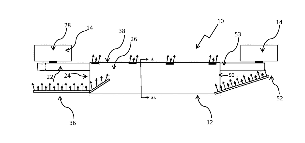
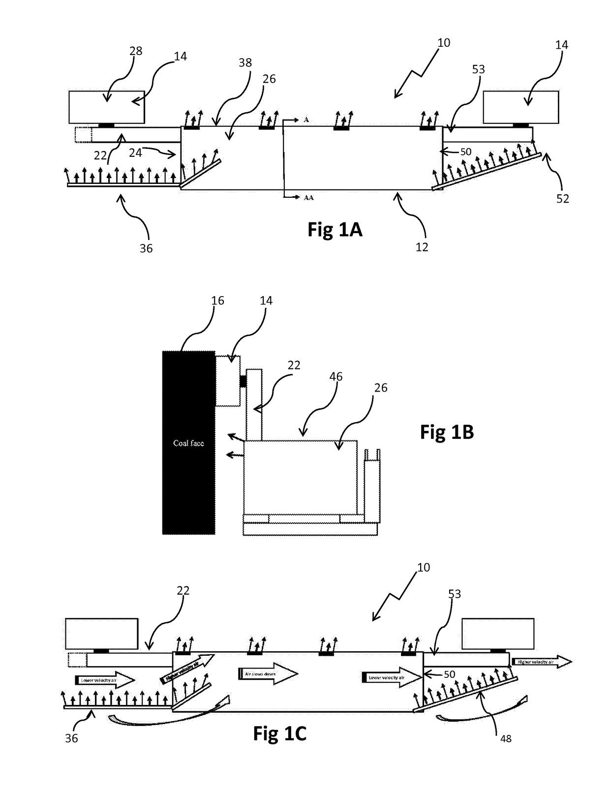
[0032]A spray system 10 is generally provided and is designed for controlling dust as shown in FIGS. 1A and 1B. When a shearer machine 12 is in operation, an at least one drum 14 generates dust when a mining wall 16 is scraped. The shearer machine 12 generally operates laterally relative to a mining floor surface to shear material from the mining wall 16 by using a conveyor system.

[0033]Referring now to FIGS. 1A, 1C, 3B, 3C, 4A and 4B, the spray system 10 is provided with a set of first ranging arm sprays 18 mounted on an upper side 20 of a first ranging arm 22. The first ranging arm 22 is located on a first end 24 of a shearer machine chassis 26 and extends several feet to support a lead drum 28 (or first drum). The lead drum 28 refers to the drum that resides on the side where air enters the operating area as shown in FIG. 1C but it is known in the art that the shearer machine 12 will operate in a reverse manner where the lead drum 28 trails the shearer machine chassis 26. The set...


PUM

PropertyMeasurementUnit
angleaaaaaaaaaa
angleaaaaaaaaaa
angleaaaaaaaaaa

Abstract

A spray system for dust control on a shearer machine that operates laterally with respect to a mining floor surface is provided where the spray system is provided with a set of first ranging arm sprays mounted on a first ranging arm and wherein said first ranging arm is located on a first end of a shearer machine chassis. A set of second ranging arm sprays is optionally provided and is mounted on the upper side of the first ranging arm and resides approximate to and in operational relationship to the set of first ranging arm sprays. Furthermore, a plurality of chassis spray sets may also be optionally provided and are located on a mining side of said shearer machine chassis and reside in a non-linear format. Moreover, a set of shearer-clearer venturi arm sprays may also optionally be provided and is mounted on a shearer-clearer venturi arm that resides as an angular extension of the set of first shearer-clearer arm sprays.

Description

BACKGROUND OF THE INVENTION[0001]Longwall mining of coal has increased substantially in the United States and currently accounts for over 50% of the underground mined coal. Increased production rates and high out-of-coal seam dilution (over 25%) in the United States and around the globe continue to generate dust control problems in mining areas. After a significant decrease in the number of incidents of coal worker's pneumoconiosis (CWP) over the last several decades, the number of reported cases in this decade is increasing. The primary cause of CWP is inhalation of respirable dust in a confined workplace; specifically, the inhalation of coal and quartz dust in a mine. The National Institute for Occupational Safety and Health (NIOSH) recognizes this disease as being severely disabling, potentially lethal, and entirely preventable through respirable (less than 10 micron) dust control. The typical protocol for prevention of this disease has been monitoring mine workers for symptoms o...

Claims


Application Information

Patent Timeline
Patent Type & Authority Applications(United States)
IPC IPC(8): E21F5/02B05B7/04E21C27/02B05B7/08B01D47/06E21C35/23
CPCE21F5/02B01D47/06E21C35/23E21C25/10B05B7/0884B05B7/0425B01D2259/45E21C27/02E21C35/22E21F5/04B08B17/02B08B15/00
Inventor CHUGH, YOGINDER P.GURLEY, HARROLD G.PULLIAM, JOHN W.
Owner SOUTHERN ILLINOIS UNIVERSITY
Why Eureka
Try Eureka