Algae Farm

a technology of algae farm and algae, applied in the field of algae farm, can solve the problems of not revealing the use of plates or water pumps, not producing enough oil at a practical scale, and not revealing the use of plates or culturing filamentous alga

Inactive Publication Date: 2017-05-11
CRICOR INC
View PDF0 Cites 15 Cited by
  • Summary
  • Abstract
  • Description
  • Claims
  • Application Information

AI Technical Summary

Benefits of technology

[0038]Embodiments of the present teachings include kits. In some configurations, a kit of the present teachings can comprise: a) a water tank: b) one or more plates or tubes, such as frosted plates or tubes; and c) a rack for suspending the one or more plates or tubes above a fill line of the water tank. In some configurations, a kit of the present teachings can further comprise algae, such as algae comprised by an algae culture. In some configurations, a kit of the present teachings can further comprise a coupon for an algae culture. In some configurations, a kit of the present teachings can further comprise a coupon for one or more fish.

Problems solved by technology

While algae have long been investigated as a potential source of biofuels, most current methods do not produce enough oil at a practical scale.
This system does not disclose the use of plates or the culturing of filamentous algae.
However, this system requires large amounts of water to allow the algae to flow from the ponds to the conveyor system, and does not disclose the use of plates or water pumps.
Furthermore, this patent teaches the use of vertically disposed fabrics and meshes as growth substrates, but does not teach or suggest the use of vertically disposed plates or tubes composed of a transparent or translucent material such as polycarbonate, acrylic or glass.
This patent does not disclose the use of recirculated water, vertical plates, or the use of filamentous algae.
However, this published application does not disclose vertical plates or tubes, or the use of filamentous algae.
This system does not disclose vertical plates or tubes, or the use of filamentous algae.
However, this patent does not disclose the growth of filamentous algae on vertical plates or tubes.
However, this system does not include vertically disposed plates or tubes with frosted surfaces.

Method used


Image

  • Algae Farm
  • Algae Farm
  • Algae Farm

Examples


example 1

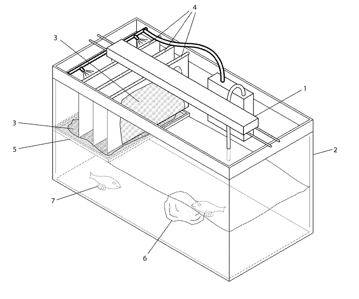
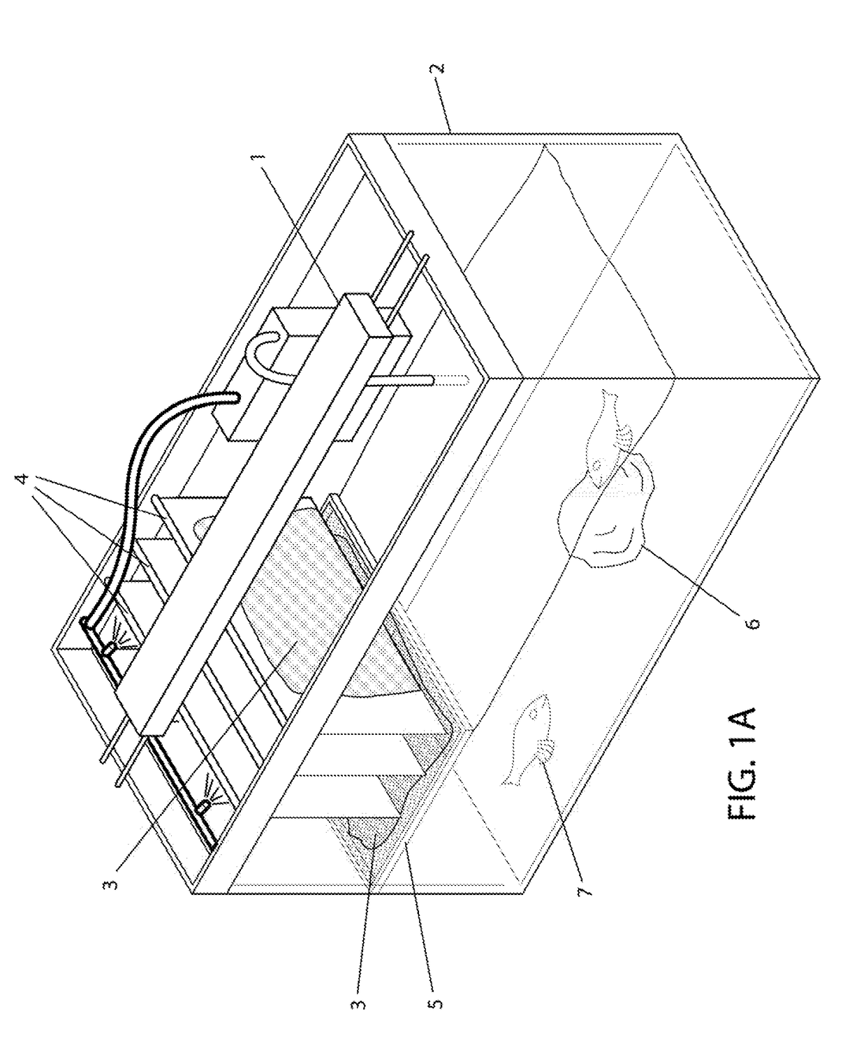
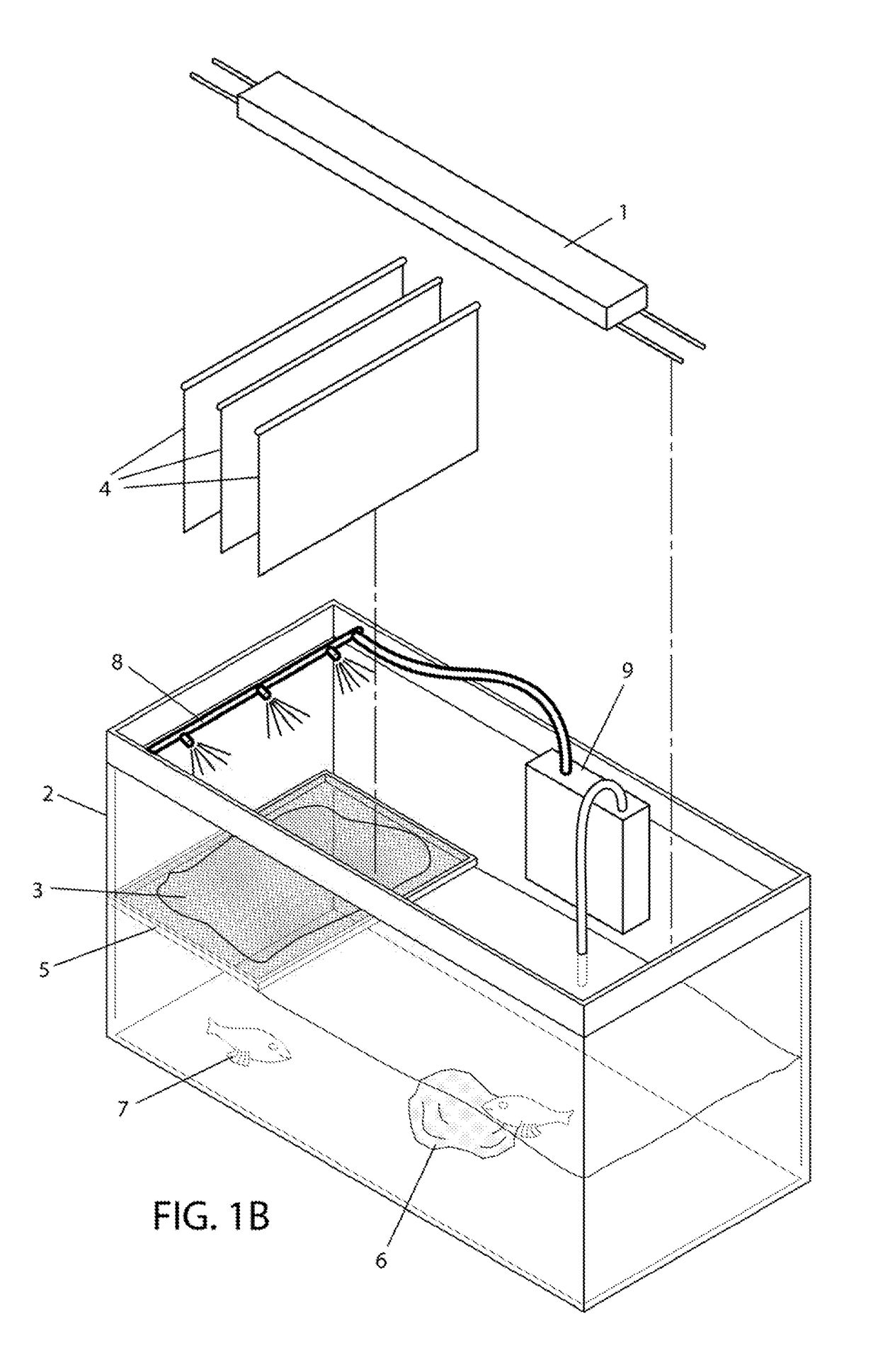
[0099]This example illustrates construction and use of a small scale system of the present teachings.

[0100]This system is depicted in use in FIG. 1A and FIG. 1B. The present inventor sanded three 8 inch by 10 inch acrylic plates (4) (FIG. 1B) and then suspended them from PVC pipes using curtain rings so that the plates extended approximately half way down into a 30 gallon fish tank (Grofizz, LLC, Austin, Tex.) (2) (FIG. 1A, FIG. 1B); the pipes rest on the rim of the fish tank. The fish tank was filled with reverse osmosis (RO) water to just below the surface of the plates. A turtle pump (9) (FIG. 1B) (Turtle Filter FX-350, EXO TERRA®, Mansfield, Mass.) was mounted on the back of the tank with a suction hose in the bottom of the tank and a spray hose above the algal plates to extract water from the bottom of the tank, through the filter, and into the spray bar (8) (FIG. 1A, FIG. 1B) made out of PVC pipes that had holes punched to form spray bars that continuously provided a flow of w...

example 2

[0101]This example describes the construction and use of a 100 gallon scale system.

[0102]Drawings of this example are provided in FIG. 2A-2G. The present inventors constructed a frame using white PVC pipe arranged as a square at top with four legs extending from each corner of the square to the floor. Two 18 in×24 in acrylic plates were prepared by sanding the surfaces until rough and then fitting the edges with red and blue LEDs (12) (FIG. 2A, FIG. 2E). These prepared plates (4) (FIG. 1B, FIG. 2A) were then suspended from the frame into a first 100 gallon tank (2a) (FIG. 2A, FIG. 2B, FIG. 2C, FIG. 2F, FIG. 2G) (RUBBERMAID®) by V-shaped metal bars (14) (FIG. 2B, FIG. 2D) attached to the plates wherein the ends were allowed to rest on the PVC pipe frame (20) (FIG. 2A, FIG. 2B). The tank was filled with water such that the lower end of the plates rested just above the water's surface. A 650 gallons per hour (GPH) water pump submerged in the bottom of the primary tank was used to pump ...

example 3

[0103]This example describes a CO2 scrubber of the present teachings.

[0104]A 12 foot by 20 foot by 100 foot first greenhouse or room is fitted with a steel frame and a 4 foot deep water tank, 4 foot by 8 foot frosted acrylic plates are suspended from the ceiling. The greenhouse is connected by a pipe to an industrial source of CO2 such as a power plant flue. The pipe further includes a control valve. A CO2 sensor is affixed to the top of the greenhouse wall approximately 1 foot from the ceiling. An O2 sensor is affixed to the wall approximately 2 feet below the CO2 sensor. The CO2 sensor is configured to close the valve connected to the CO2 source if the CO2 sensor detects CO2 concentration at or above a threshold level. The O2 sensor is configured to open the valve connected the CO2 source if the O2 sensor detects O2 concentration reaching a threshold level. These two sensors are configured such that as the room fills with CO2, the valve closes, thereby limiting CO2 concentration i...


PUM

PropertyMeasurementUnit
wavelength rangesaaaaaaaaaa

Abstract

Apparatuses and methods for growing filamentous algae are disclosed. An apparatus comprises vertical surfaces such as plates or tubes which are suspended above the fill line of a water tank. Surfaces can have a frosted texture for algal growth. The surfaces are kept moist by pumping water from the tank through spray bars to the surfaces. Sprayed water drips back into the water tank. Algae growing on a surface can be processed into products such as biofuel and glycerin. Aquatic animals such as fish can be grown in a tank. An aquatic animal can generate nitrogenous waste as nutrient for algae, and provide food for human consumption. The amount of harvestable algae produced by an apparatus can exceed the amount produced from other systems of comparable size over comparable durations. An apparatus can also be utilized to scrub CO2.

Description

CROSS REFERENCE TO PRIOR APPLICATION[0001]This application claims benefit of and priority to U.S. Provisional Application 62 / 253,851, filed on Nov. 11, 2015. This application is hereby incorporated by reference in its entirety.INTRODUCTION[0002]As the earth's supply of fossil fuels slowly dwindles, new, renewable sources of energy are urgently required. One potential class of fuels are plant-based fuels. The most common of these fuels are ethanol and biodiesel derived from corn and soy. While algae have long been investigated as a potential source of biofuels, most current methods do not produce enough oil at a practical scale. For example, a typical 650 L unicellular algae pond only yields about one ounce of oil.[0003]U.S. Pat. No. 8,753,851 to Stephen et al. describes a system in which algae and bivalves are co-cultured in enclosures comprising water with recycled nutrients and separate enclosures for culturing fishes that harvest the algae by eating them. This system requires the...

Claims


Application Information

Patent Timeline
Patent Type & Authority Applications(United States)
IPC IPC(8): A01K63/00C02F3/32A01G33/00A01K63/04A01G1/00
CPCA01K63/006A01K63/045A01G1/001C02F2103/20A01K63/042C02F3/325A01G33/00C02F3/006C02F3/06C02F3/327Y02W10/37Y02A40/80Y02W10/10C12M1/002
Inventor BEE, RICHARDGOCHANOUR, CHRISTOPHER W.
Owner CRICOR INC
Why Eureka
Try Eureka