Multi-die melt blowing system for forming co-mingled structures and method thereof

Inactive Publication Date: 2017-05-18
GROZ BECKERT KG
View PDF2 Cites 8 Cited by
  • Summary
  • Abstract
  • Description
  • Claims
  • Application Information

AI Technical Summary

Benefits of technology

The present invention provides a system that can create a unique nonwoven structure using different types and sizes of fibers. This system can also trap a third component within the nonwoven structure. The system uses multiple die types and configurations, which allows for the use of different polymers and the creation of strong and durable structures. The third component can be a variety of materials, such as powder, continuous fiber, electrospun fiber, or particles. The fibers can be small or large in diameter and can have high surface area. Overall, the system can produce a nonwoven structure with specific properties and characteristics.

Problems solved by technology

Although it is possible to form meltblown structures from polybutylene terephthalate (PBT), polyethylene terephthalate (PET), Nylons and other fiber grade polymers, the higher viscosities of these polymers leads to larger fibers, which can be undesirable in meltblown fabrics as meltblown structures are commonly used in filtration applications ranging from HVAC filters to facemasks and respirators to liquid filtration.
Consequently, conventional meltblown fibers are fine and the fabrics formed therefrom are weak and have limited extensibility.
Therefore, conventional meltblown structures can be difficult to pleat and / or mold.

Method used


Image

  • Multi-die melt blowing system for forming co-mingled structures and method thereof
  • Multi-die melt blowing system for forming co-mingled structures and method thereof
  • Multi-die melt blowing system for forming co-mingled structures and method thereof

Examples


example 1

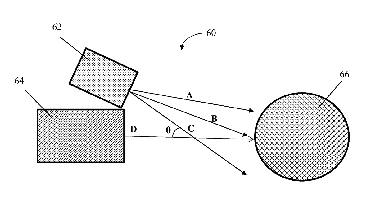
[0101]Co-mingled fine and coarse fibers can be formed by having two or more dies that have capillaries that are different in size. Alternatively, two or more similar or dissimilar dies can be used but the capillary throughput is adjusted such that fine and coarse fibers are formed. In a preferred embodiment, two different die types are used—one based on a concentric air design and the other based on single-row-drilled-hole type die design.

example 2

[0102]Co-mingled meltblown and electrospun webs can be formed by having two or more meltblown dies and a stream of electrospun fibers that are injecting the electrospun fiber webs into the meltblown fiber streams. The drum collector acts as the ground for the Electrospinning system. The advantage of such a system is that it can form a larger fiber layer (for pleating / molding) and also for pre-filtering using a concentric air-type die and a polymer such as PET, PBT and the like, and a layer of electrospun fibers that are deposited into the middle of the of the two converging meltblown fiber streams. As such, a third layer of fibers can be inserted between and / or at least partially co-mingled with layers of fine fiber.

example 3

[0103]Co-mingled cut fibers and meltblown fibers can be formed by having two or more meltblowing dies and depositing cut fibers in the form of loose fibers and / or staple fiber webs by depositing fibers and / or the web into the converging stream of meltblown fibers. The fibers are deposited by using a similar technique to depositing particles in powder coating units where they are dosed and added using a rotating brush or collector.


PUM

PropertyMeasurementUnit
Lengthaaaaaaaaaa
Lengthaaaaaaaaaa
Lengthaaaaaaaaaa

Abstract

A melt blowing system for the manufacturing of pleatable / moldable nonwoven fabrics includes a collector positioned to receive a plurality of fibers, a first die in fluid communication with a first liquid polymer supply having a melt flow index of about 500 or lower, and a second die in fluid communication with a second liquid polymer supply having a melt flow index of about 500 or higher. The first die has a concentric air design, includes a plurality of spinneret nozzles facing the collector surface, and is configured to draw a first plurality of fibers. The second die includes a plurality of spinneret nozzles having smaller capillary diameter than those of the first die and is positioned to draw a second plurality of fibers such that the first and second pluralities of fibers form a co-mingled nonwoven web with varying fiber diameters on the collector surface.

Description

FIELD OF THE INVENTION[0001]The present invention relates to a melt blowing system comprising two or more dies that can be configured to form co-mingled nonwoven structures, as well as comingled nonwoven structures formed using such a system that will incorporate particles and other additives into the web.BACKGROUND OF THE INVENTION[0002]Synthetic fibers are widely used in a number of diverse applications to provide stronger, thinner, and lighter weight products. Furthermore, synthetic thermoplastic fibers are typically thermobondable and thus are particularly attractive for the manufacture of nonwoven fabrics, either alone or in combination with other non-thermoplastic fibers (such as cotton, wool, and wood pulp, for example). Nonwoven fibrous networks, in turn, are increasingly used as a substitute for conventional woven textiles due in part to their low cost of production. The nonwoven fibers are initially presented as unbound fibers or filaments, which may be natural or man-made...

Claims


Application Information

Patent Timeline
IPC IPC(8): D01D4/02D01D5/08D04H1/4382B01D39/08D04H1/435D04H1/56D04H1/724D04H1/732D01D5/098D04H1/4291
CPCD01D4/025D01D5/0985D01D5/082D04H1/4382D04H1/4291D04H1/435B01D2239/0622D04H1/724D04H1/732B01D39/083D10B2505/04B01D2239/0618D04H1/56D04H1/43838D04H1/43835D04H3/153
Inventor POURDEYHIMI, BEHNAMSHIM, EUNKYOUNG
Owner GROZ BECKERT KG
Why Eureka
Try Eureka