System and Method for Determining Poor Sensor Contact in a Multi-Sensor Device

Inactive Publication Date: 2017-05-25
LACAMAS LIFE SCI INC
View PDF1 Cites 5 Cited by
  • Summary
  • Abstract
  • Description
  • Claims
  • Application Information

AI Technical Summary

Benefits of technology

[0015]Described herein are systems and methods for detecting poor sensor contact in a vital sign measurement system that measures both ECG (electrocardiogram) and PPG (photoplethysmography) signals. The method can detect if either of the sensors, or both of the sensors, are not making good contact with the user. If a sensor is not making good contact, then the related vital sign measurement will also have poor quality, as the system receives significant noise. The method receives signal status in

Problems solved by technology

If a sensor is not making good contact, then the related vital sign measure

Method used


Image

  • System and Method for Determining Poor Sensor Contact in a Multi-Sensor Device
  • System and Method for Determining Poor Sensor Contact in a Multi-Sensor Device
  • System and Method for Determining Poor Sensor Contact in a Multi-Sensor Device

Examples


Example

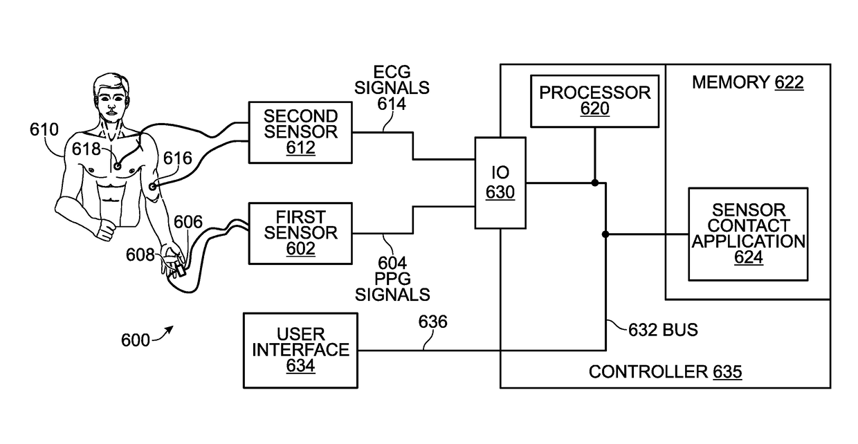
[0042]FIG. 6 is a schematic block diagram of a system for determining sensor contact in a multi-sensor device. The system 600 comprises a first sensor 602 having an output on line 604 to supply measured photoplethysmography (PPG) signals. Typically, the first (PPG) sensor 602 comprises a light emission device 606 and a light sensing device 608 for detecting changes in an optical transmittance of an illuminated test subject body 610. A second sensor 612 has an output on line 614 to supply measured electrocardiogram (ECG) signals. Typically, the second (ECG) sensor 612 comprises at least two electrodes 616 and 618.

[0043]The system 600 further comprises a processor 620 and a non-transitory memory 622. A sensor contact application 624 resides in the non-transitory memory 622 and comprises a sequence of processor instructions. The sensor contact application 624 receives the PPG and ECG signals, detects a correlation in time between PPG signals and corresponding ECG signals. The ECG and P...


PUM


Abstract

A system and method are provided for determining sensor contact in a multi-sensor device. The method measures a series of photoplethysmography (PPG) heart beat signals, while simultaneously measuring a series of electrocardiogram (ECG) heart beat signals. The method detects a correlation in time between each of a plurality of PPG signals and corresponding ECG signals. In response to the timing between correlated PPG and ECG signals remaining within a first correlation deviation limit, a correlation state is determined. For example, a correlation state may be determined in response to a out of m number of correlated PPG and ECG signals remaining within the correlation deviation limit, where n and m are integers greater than zero.

Description

BACKGROUND OF THE INVENTION[0001]1. Field of the Invention[0002]This invention generally relates to health monitoring and, more particularly, to a system and method for determining when vital sign monitoring sensors are making poor contact with a patient being monitored.[0003]2. Description of the Related Art[0004]Electrocardiography (ECG or EKG) is the process of recording the electrical activity of the heart over a period of time using electrodes placed on a patient's body. These electrodes detect the tiny electrical changes on the skin that arise from the heart muscle depolarizing during each heartbeat. During each heartbeat, a healthy heart has an orderly progression of depolarization that starts with pacemaker cells in the sinoatrial node, spreads out through the atrium, passes through the atrioventricular node down into the bundle of His and into the Purkinje fibers spreading down and to the left throughout the ventricles. This orderly pattern of depolarization gives rise to t...

Claims


Application Information

Patent Timeline
IPC IPC(8): A61B5/00A61B5/0408A61B5/024
CPCA61B5/6843A61B5/02416A61B5/7221A61B5/7246A61B5/7475A61B5/0408A61B5/0245A61B2560/0276A61B5/30A61B5/25
Inventor HALLBERG, BRYAN
Owner LACAMAS LIFE SCI INC
Why Eureka
Try Eureka