Fourier ptychographic microscopy with multiplexed illumination

Inactive Publication Date: 2017-05-25
RGT UNIV OF CALIFORNIA
View PDF4 Cites 42 Cited by
  • Summary
  • Abstract
  • Description
  • Claims
  • Application Information

AI Technical Summary

Benefits of technology

[0015]In order to reach the goal of sub-second capture times, the capture strategy exploits the redundancy in FPM data by using multiplexed illumination schemes which require significantly fewer images. The redundancy arises because of a requirement that the Fourier space area for each neighboring LED be overlapped by at least 60% in order to ensure algorithm convergence. This means that approximately ten times more data must be capture

Problems solved by technology

Even though the spatial resolution of each measurement may be poor, the images coll

Method used


Image

  • Fourier ptychographic microscopy with multiplexed illumination
  • Fourier ptychographic microscopy with multiplexed illumination
  • Fourier ptychographic microscopy with multiplexed illumination

Examples


example 1

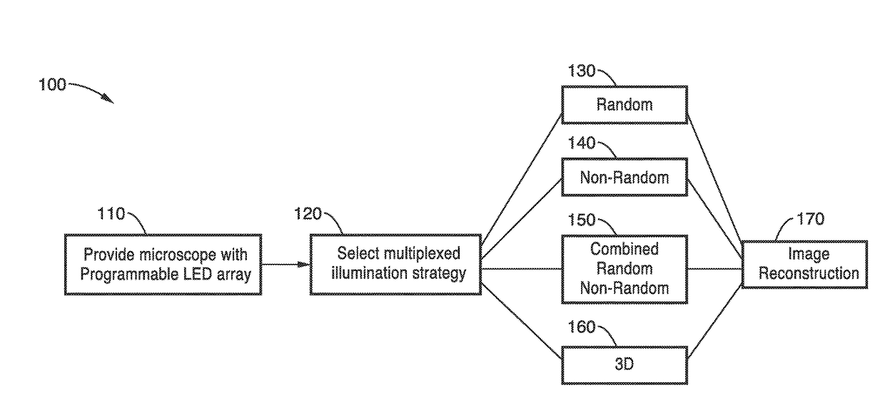
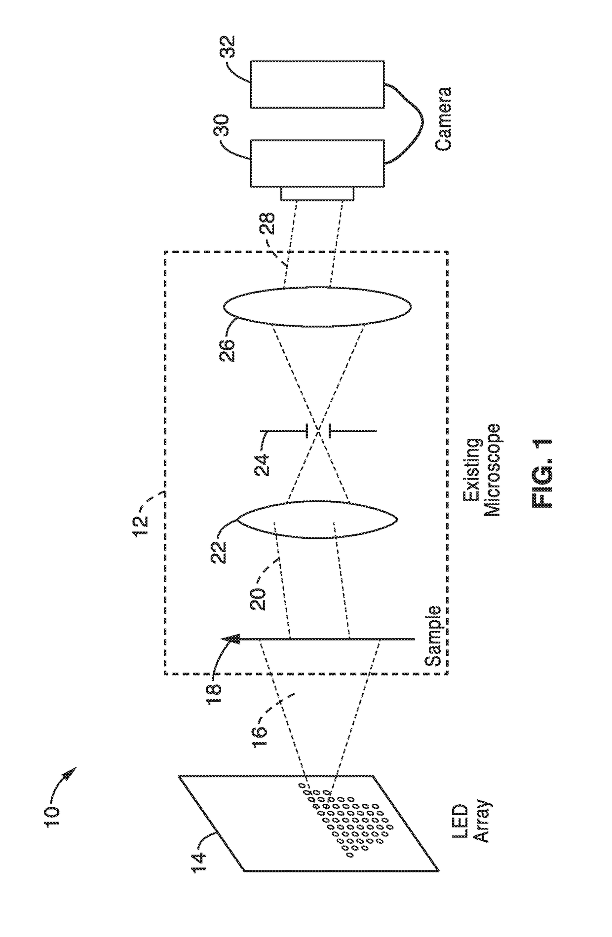
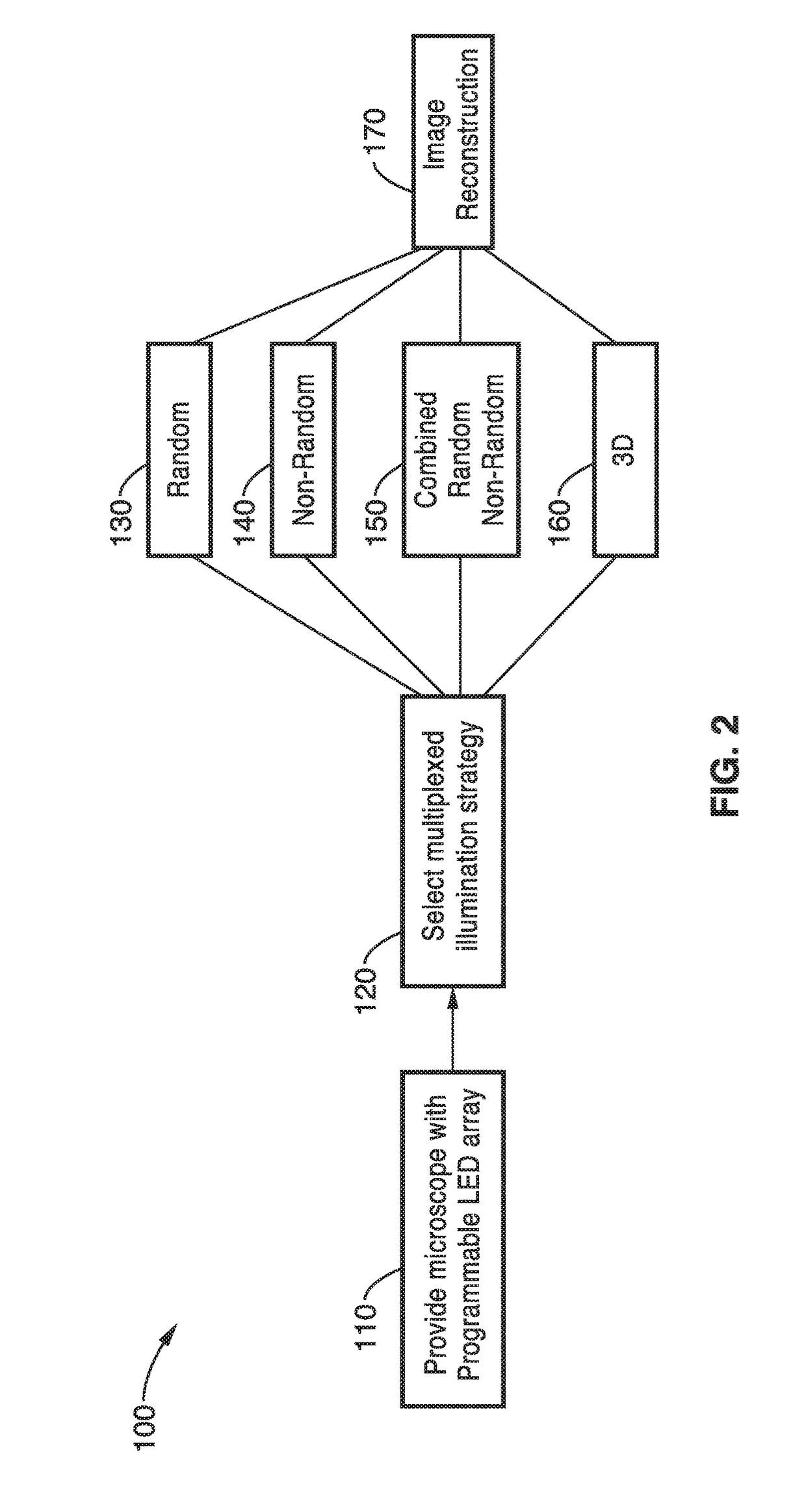
[0113]In order to demonstrate a random multiplexed illumination strategy, where multiple randomly selected LEDs are turned on for each image, an apparatus as schematically shown in FIG. 1 with a programmable LED array was assembled. All samples were imaged with a 4×0.1 NA objective and a scientific CMOS camera. A programmable 32×32 LED array (Adafruit, 4 mm spacing, controlled by an Arduino) was placed at 67.5 mm above the sample to replace the light source on a Nikon TE300 inverted microscope. The central 293 red (central wavelength 629 nm and 20 nm bandwidth) LEDs were used resulting in a final synthetic NA of 0.6. In principle, the LED array could provide larger NA improvements, but it is practically limited by noise in the dark field images from high angle LEDs.

[0114]Since each LED corresponds to a different area of Fourier space, the total number of images can be significantly reduced, without sacrificing image quality. The method was demonstrated experimentally in a modified c...

example 2

[0121]To demonstrate the non-random illumination methods, an LED array microscope with a 32×32 custom-made LED array (4 mm spacing, central wavelength 513 nm with 20 nm bandwidth) placed 63 mm above the sample was used to replace the microscope's standard illumination unit. The LED array was controlled by an ARM microcontroller and synchronized with the camera to switch the LED patterns at camera-limited speed. The camera operated at 50 Hz with full-frame (2160×2560) 16 bit images allowing single-axis DPC measurements at 25 Hz. Example images all used Hela cell samples imaged by a 20×0.4 NA objective.

[0122]The phase transfer function can be tuned by using different illumination patterns. DPC is commonly implemented with half-circle shape illumination patterns. DPC requires illumination from high angles for good phase recovery at all spatial frequencies. As the illumination NA increases (measured by the coherence parameter a), additional low spatial frequency and high spatial frequen...

example 3

[0127]To further demonstrate the operational principles of the methods, a system of an inverted microscope with a programmable 32×32 individually addressable LED array to pattern illumination angles was assembled.

[0128]All LEDs were driven statically using 64 LED controller chips (MBI5041) to provide an independent drive channel for each LED. A controller unit based on the ARM 32-bit Cortex M3 CPU provides the logical control for the LED array by the I2C interface at 5 MHz. The LED pattern transfer time is about 320 ps. A standard stage-mounted incubator was used for imaging live cell samples in a petri dish.

[0129]For specimens, HeLa cells, Human osteosarcoma epithelial (U2OS) cells and human mammary epithelial (MCF10A) cells were cultured with DMEM (Dulbeccos Modified Eagles Medium) supplemented with 10 % FBS (fetal bovine serum), Glutamine and penicillin / streptomycin. The cells were plated on p75 flasks and cultured in 37 degree incubator with 5% CO2.

[0130]The random, non-random a...


PUM


Abstract

A system and methods for wide field of view, high resolution Fourier ptychographic microscopic imaging with a programmable LED array light source. The individual lights in the LED array can be actuated according to random, non-random and hybrid random and non-random illumination strategies to produce high resolution images with fast acquisition speeds. The methods greatly reduce the acquisition time and number of images captured compared to conventional sequential scans. The methods also provide for fast, wide field 3D imaging of thick biological samples.

Description

CROSS-REFERENCE TO RELATED APPLICATIONS[0001]This application is a 35 U.S.C. §111(a) continuation of PCT international application number PCT / US2015 / 031645 filed on May 19, 2015, incorporated herein by reference in its entirety, which claims priority to, and the benefit of, U.S. provisional patent application Ser. No. 62 / 000,520 filed on May 19, 2014, incorporated herein by reference in its entirety. Priority is claimed to each of the foregoing applications.[0002]The above-referenced PCT international application was published as PCT International Publication No. WO 2015 / 031645 on Nov. 26, 2015, which publication is incorporated herein by reference in its entirety.STATEMENT REGARDING FEDERALLY SPONSORED RESEARCH OR DEVELOPMENT[0003]Not Applicable.INCORPORATION-BY-REFERENCE OF COMPUTER PROGRAM APPENDIX[0004]Not ApplicableBACKGROUND[0005]1. Technical Field[0006]The present technology pertains generally to optical imaging and more particularly to a brightfield microscope with a program...

Claims


Application Information

Patent Timeline
IPC IPC(8): G02B21/36G02B21/12G06T7/11G02B21/14H04N5/225G06T19/20
CPCG02B21/367H04N5/2256G02B21/125G06T7/11G02B21/14G06T19/20G06T5/50G06T2207/10056G06T2207/10152G06T2207/20221G02B27/58G03H2001/0456H04N23/56
Inventor WALLER, LAURATIAN, LEI
Owner RGT UNIV OF CALIFORNIA
Why Eureka
Try Eureka