
Electron emitter source

a technology of emitter and emitter body, which is applied in the direction of discharge tube/lamp details, x-ray tubes, electrostatic control tubes, etc., can solve the problems of reducing the performance of the emitter, angular intensity, and negative impact on the key properties of the emitter

Active Publication Date: 2017-05-25
OREGON PHYSICS +1
View PDF30 Cites 6 Cited by
  • Summary
  • Abstract
  • Description
  • Claims
  • Application Information

AI Technical Summary

Benefits of technology

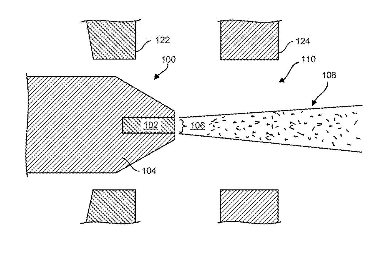
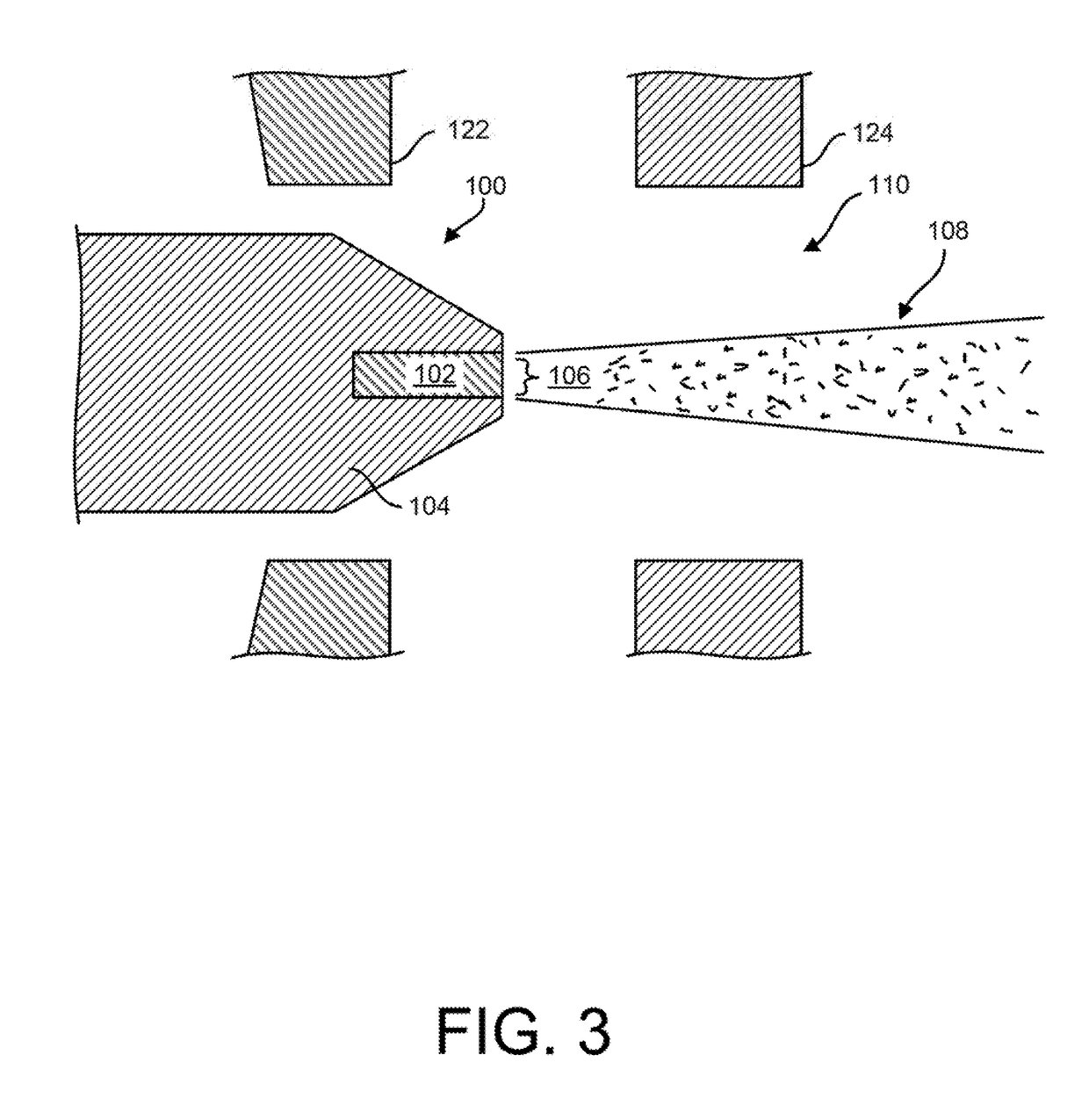
The invention is about an electron emitter that consists of a low work function material (such as Lanthanum hexaboride or Iridium Cerium) embedded in a high work function material (such as titanium or iridium) that acts as a cylinder base. The combined structure is heated and biased with a negative voltage relative to an anode. The emitter has a conical shape with the end containing the emissive area placed between the anode and a wehnelt electrode with an aperture. In one aspect, a gap or chamfer is placed at the interface of the exposed low work function material and the surrounding high work function material. In another aspect, the end of the cone is placed between the wehnelt and the anode. The technical effect of this invention is to provide an electron emitter with improved electron emission efficiency and stability.

Problems solved by technology

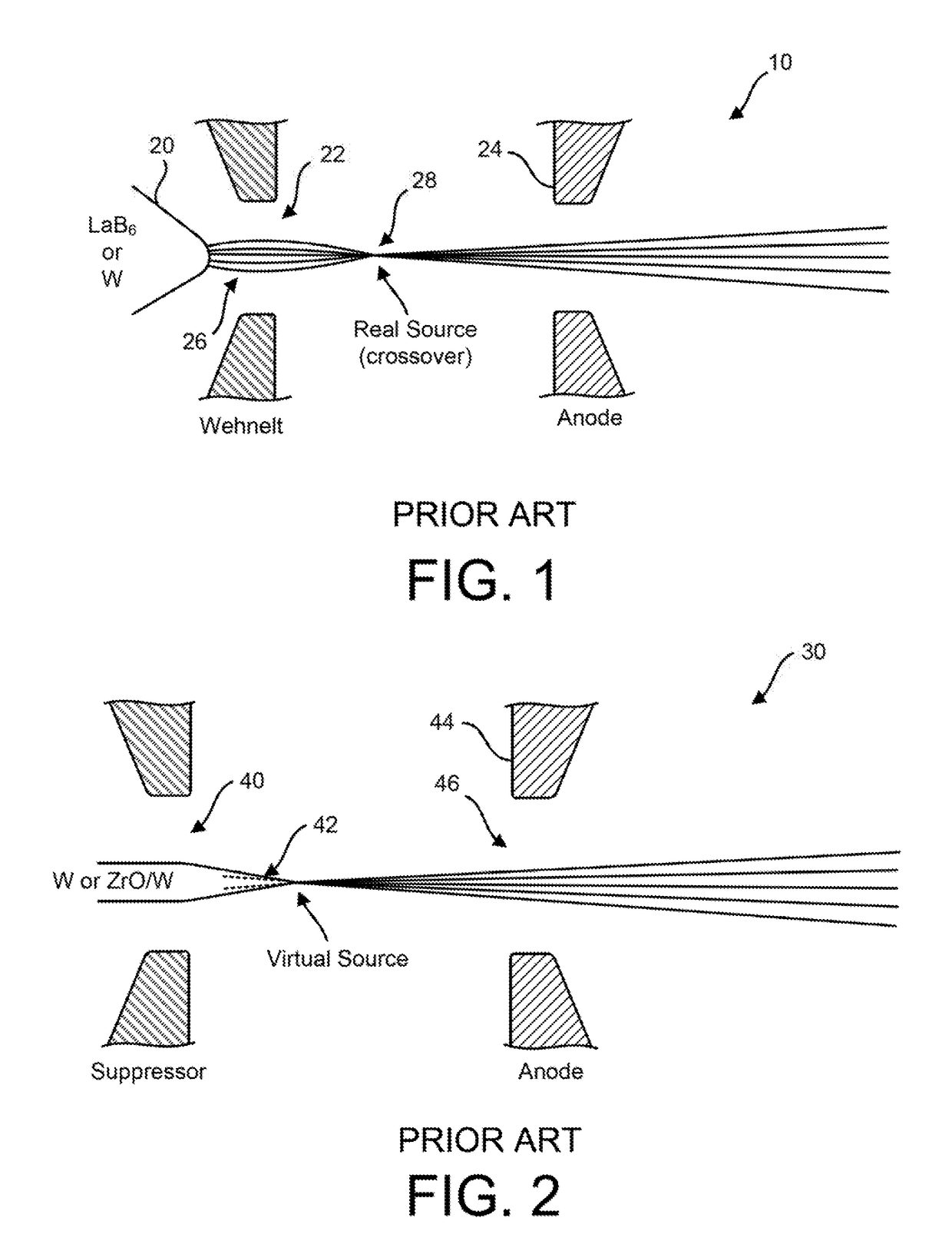
However, since the emission area is small these emitters have low current, low angular intensity, and a narrow emission angle
The large amount of current produced outside the desired cone is problematic and reduces the performance of the emitter, thus having a negative impact on the key properties of the emitter.
However, the field emitter of FIG. 2 also has a disadvantage because the emitting surface is only that small rounded tip of the sharpened emitter 42 where the electrons are emitted, thus resulting in a smaller emission.

Method used


Image

  • Electron emitter source
  • Electron emitter source
  • Electron emitter source

Examples


embodiment 100

[0032]FIG. 4 shows an alternate embodiment of the emitter 200 where like features have the same numbering as in the original inventive embodiment 100. The emitter 102 is formed of a 20-100 micron diameter cylinder of low work function material, and having a length greater than 50 microns. Suitable low work function material includes Lanthanum hexaboride or Iridium Cerium. This cylinder 102 is embedded in a high work function material that could be a cylinder 104 with diameter between 100-1000 microns that has a machined cone 112 on the end. One suitable material for the high work function material is high purity graphite. The cone has a 50-400 micron diameter flat 114 at the end that has a hole 116 drilled near the center where the low work function cylinder 102 is inserted. The cone half angle A is preferably between 5 to 85 degrees and more preferably between 20 and 70 degrees. The hole is drilled in the high work function material such that the low work function cylinder has a ti...

embodiment 500

[0038]FIG. 7 shows an alternate embodiment 500 of the emitter, which includes drilling one or more vent holes 532 from edge of the embedded emitter 102 to the edge of the graphite cylinder 104. The vent hole improves the vacuum near the emitter by providing an exit path for trapped gases or gas byproducts of reactions that occur at elevated temperatures. A useful vent hole is preferably between about 50-100 microns in diameter.

[0039]FIG. 8 shows yet another alternate embodiment 600 where like features have the same numbering as in the original inventive embodiment 100. The emitter 102 is formed of a 20-100 micron diameter cylinder of low work function material, and having a length greater than 50 microns. This cylinder 102 is embedded in a high work function material that could be a cylinder 604 with diameter between 100-1000 microns terminating in a cylinder end 614 on the end. One suitable material for the high work function material is high purity graphite. As with the embodiment...


PUM


Abstract

An electron emitter that consists of: a low work function material including Lanthanum hexaboride or Iridium Cerium that acts as an emitter, a cylinder base made of high work function material that has a cone shape where the low work function material is embedded in the high work function material but is exposed at end of the cone and the combined structure is heated and biased to a negative voltage relative to an anode, an anode electrode that has positive bias relative to the emitter, and a wehnelt electrode with an aperture where the cylindrical base protrudes through the wehnelt aperture so the end of the cone containing the emissive area is placed between the wehnelt and the anode.

Description

CROSS-REFERENCES TO RELATED APPLICATIONS[0001]This application claims the benefit of U.S. Provisional Patent Application No. 62 / 257,732, filed Nov. 20, 2015, whose contents are incorporated herein for all purposes.BACKGROUND OF THE INVENTION[0002]Field of the Invention[0003]This invention relates generally to thermal emission sources and more particularly to electron emitters that exhibit high angular intensity and small virtual source size.[0004]Description of the Prior Art[0005]Free electrons that are generated in vacuum are used in many practical devices including Cathode Ray tubes, X-ray machines, electron microscopes, and e-beam lithography tools. Specialized electron emitters that can generate intense directed beams of electrons with specific properties have been developed for these applications. The properties that are important for these emitters are the angular intensity (i.e., the amount of electron current contained in a given emission angle), the emission cone angle size...

Claims


Application Information

Patent Timeline
Patent Type & Authority Applications(United States)
IPC IPC(8): H01J19/10H01J21/06H01J19/068H01J19/38H01J19/32
CPCH01J19/10H01J19/38H01J21/06H01J19/068H01J19/32H01J1/148H01J3/024H01J37/065H01J2237/06308H01J2237/06375H01J35/064H01J35/066H01J19/82
Inventor TESCH, PAUL P.MAGERA, GERALD G.
Owner OREGON PHYSICS
Learn More