
Inertial navigation system

a technology of navigation system and inner circle, applied in the direction of navigation instruments, process and machine control, instruments, etc., can solve the problems of kalman filtering, earlier systems have struggled to cope with the high roll rate, and the most significant source of error, so as to achieve low cost, less expensive components, and high scale factor error

Active Publication Date: 2017-06-08
ATLANTIC INERTIAL SYST
View PDF23 Cites 20 Cited by
  • Summary
  • Abstract
  • Description
  • Claims
  • Application Information

AI Technical Summary

Benefits of technology

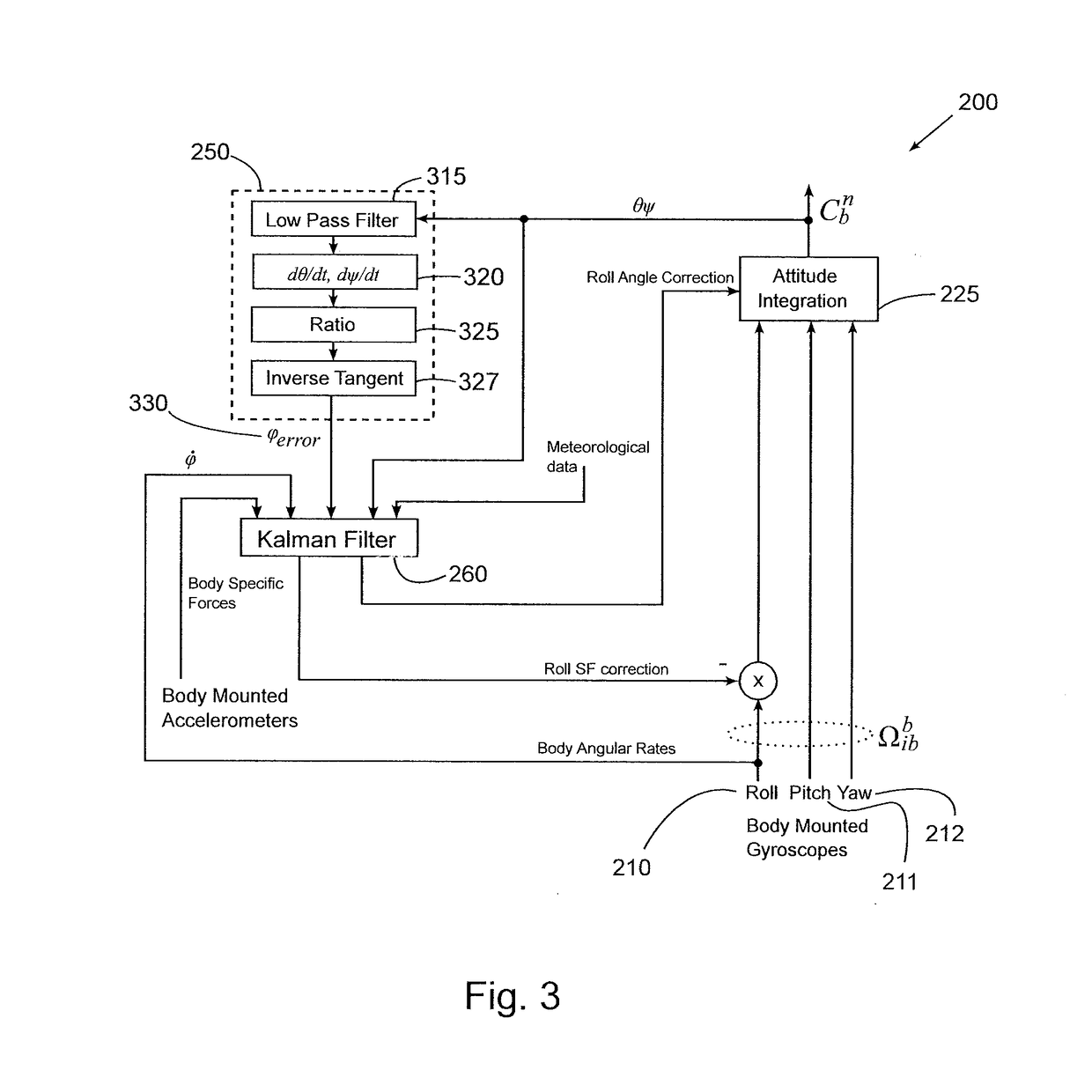
The patent describes a new system for stabilizing a filter used in existing systems. The new system uses a separate process to calculate an estimate of the roll angle error, which is then provided as an input to the filter. This results in a more accurate estimate of the roll rate scale factor error and improves the filter's stability and performance. The system can accommodate a broader range of different missions and can estimate and correct for crosswind effects, which can significantly improve performance. The filter uses time-varying gains and is tailored for specific trajectories. The system also includes a roll gyro, which can be a MEMS gyro, with a high scale factor error that can be tolerated through the feedback system. This allows for the use of lower quality components, reducing the cost of the system while maintaining excellent accuracy.

Problems solved by technology

As discussed above, the errors in the roll rate measurement are the most significant source of error in high roll rate navigation systems.
Earlier systems have struggled to cope with the high roll rates that are present in the earliest phase of flight, i.e. immediately after launch, and attempts have been made to mitigate these effects.
In particular, existing systems that use Kalman filters have struggled to achieve stability in the filter due to the high roll rates and the rapid accumulation of roll angle error.

Method used


Image

  • Inertial navigation system
  • Inertial navigation system
  • Inertial navigation system

Examples


Embodiment Construction

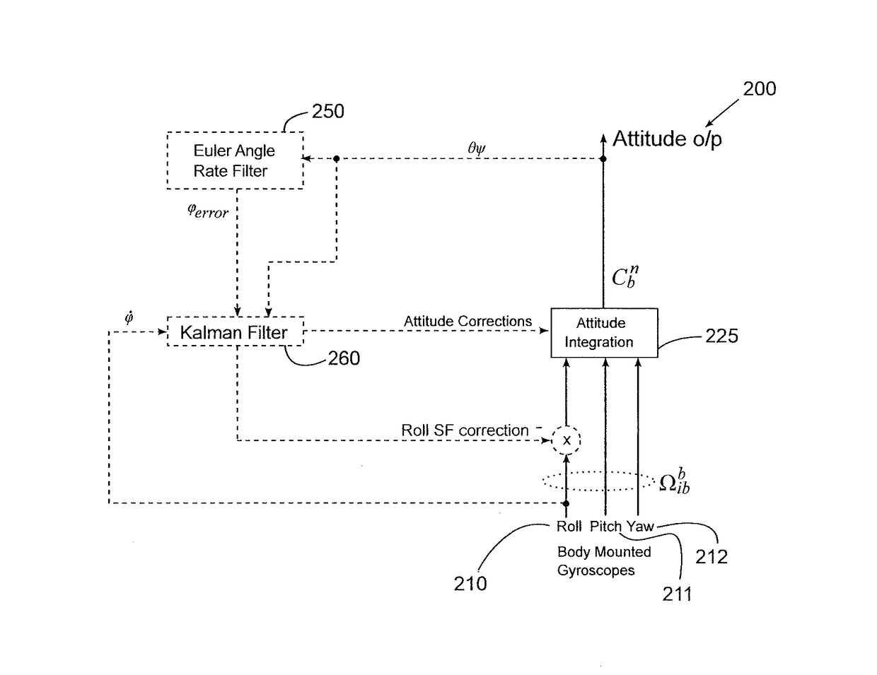
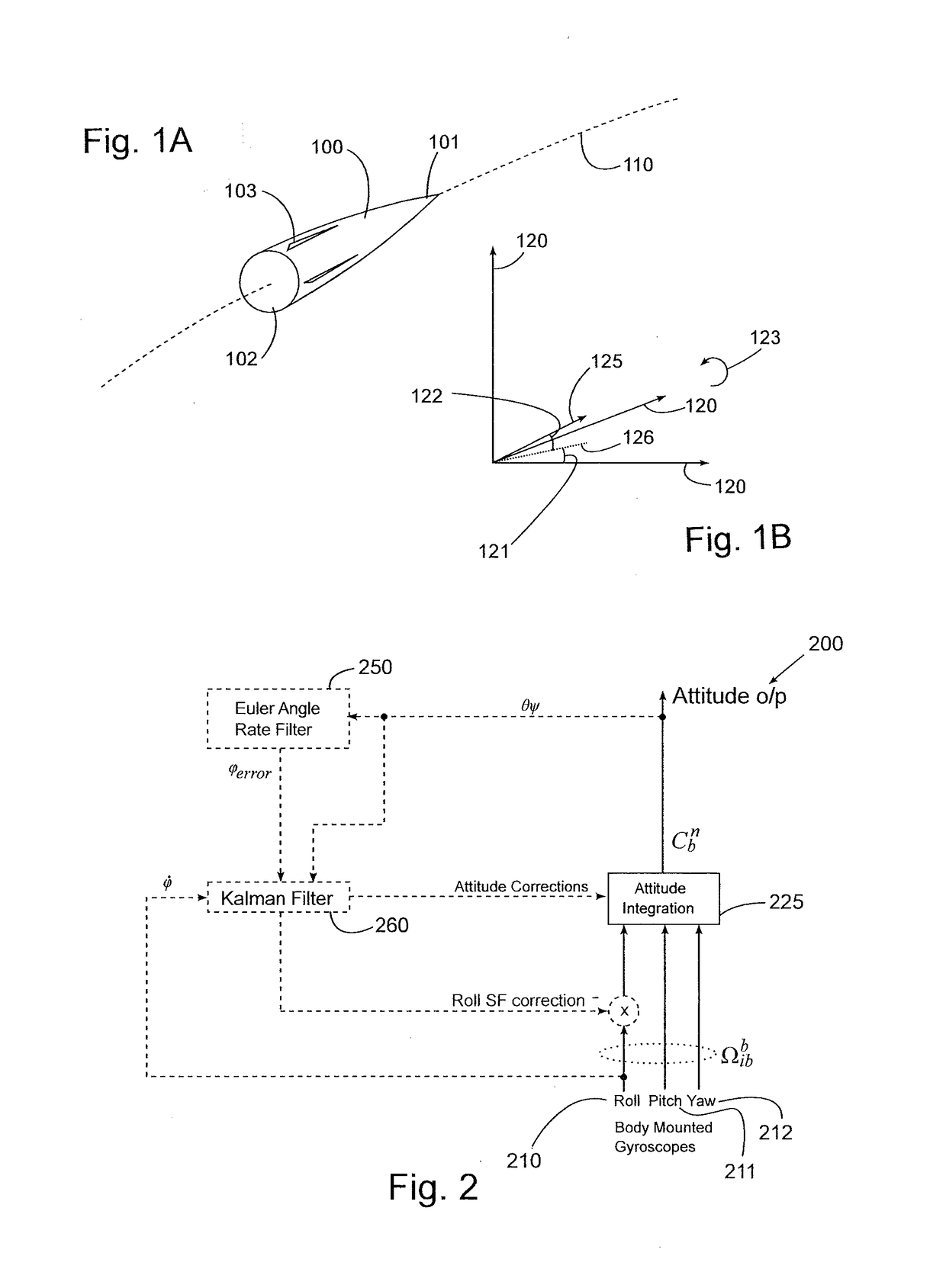
[0045]The following describes a method to perform in-flight calibration of (i.e. to measure and correct) the roll axis rate gyro scale factor for an Inertial Measurement Unit (IMU) fitted to a rolling projectile 100.

[0046]FIG. 1A illustrates a rocket 100 in flight. Its trajectory 110 is shown in broken line. The rocket 100 has a nose 101, tail 102 with fins 103. Fins 103 may be static or they may be movable so as to provide directional control so as to alter the flight path of the rocket 100.

[0047]In inertial navigation terminology, the orientation of a body / platform is described in terms of the three Euler angles ‘heading, ‘elevation’ and ‘bank’. The equivalent terms ‘yaw’, ‘pitch’ and ‘roll’ are also in use. The body orientation is generally referred to using the term ‘attitude’. Although strictly speaking the term ‘attitude’ refers only to the elevation and bank angles, in this document, the more general definition is used. Therefore in this document, the term ‘attitude’ refers t...


PUM


Abstract

An inertial measurement system for a spinning projectile comprising: a first, roll gyro to be oriented substantially parallel to the spin axis of the projectile; a second gyro and a third gyro with axes arranged with respect to the roll gyro such that they define a three dimensional coordinate system; a controller, arranged to: compute a current projectile attitude from the outputs of the first, second and third gyros, the computed attitude comprising a roll angle, a pitch angle and a yaw angle; calculate a roll angle error based on the difference between the computed pitch and yaw angles and expected pitch and yaw angles; provide the roll angle error as an input to a Kalman filter that outputs a roll angle correction and a roll rate scale factor correction; and apply the calculated roll angle correction and roll rate scale factor correction to the output of the roll gyro; wherein the Kalman filter models roll angle error as a function of roll rate and one or more wind variables. The system provides improved calibration of the roll axis rate gyro scale factor, e.g. of an IMU fitted to a rolling projectile. A separate process (an Euler angle filter) is used to calculate an estimate of the roll angle error without the use of the Kalman filter and is then provided as an input to the Kalman filter which can then operate in a stable manner. The filter can be configured to estimate and correct for crosswind effects which would otherwise significantly degrade performance.

Description

[0001]This application claims priority to Great Britain Appln. No. 1521539.5 filed Dec. 7, 2015, which application is hereby incorporated by reference.BACKGROUND OF THE INVENTION[0002]1. Technical Field[0003]This disclosure relates to inertial navigation systems, in particular those used for projectiles e.g. guided rockets. Inertial navigation systems can be used on guided projectiles to provide position information which can in turn be used to correct the projectile's course to keep it on target. 2. Background Information[0004]Navigation systems can use a variety of different sensors to detect changes to the motion and orientation of an object. For example accelerometers, gyros and magnetometers are often used. Accelerometers detect applied force, gyros detect rotation rates and magnetometers detect the Earth's magnetic field and so can be used to determine absolute orientation.[0005]Inertial navigation systems, based on accelerometers and gyroscopes, can be used either on their ow...

Claims


Application Information

Patent Timeline
Patent Type & Authority Applications(United States)
IPC IPC(8): G01P13/02F42B15/01G01C21/16
CPCG01P13/025F42B15/01G01C21/16G05D1/108G01C25/005F41G7/36G01C21/183G01C19/025G06T7/277F41G9/00B81B2201/0242G01C21/18
Inventor SHEARD, JOHN KEITHFAULKNER, NICHOLAS MARK
Owner ATLANTIC INERTIAL SYST
Learn More