Organic compound and organic electroluminescent element comprising same

a technology of organic compound and organic electroluminescent element, which is applied in the direction of luminescent compositions, organic chemistry, chemistry apparatus and processes, etc., can solve the problems of material failure to reach a satisfactory level, reduce the lifetime of the device, and the host energy gap is wide, so as to achieve the effect of improving the lifetime, excellent thermal stability, and improving the efficiency

Active Publication Date: 2017-06-15
DOOSAN SOLUS CO LTD
View PDF4 Cites 7 Cited by
  • Summary
  • Abstract
  • Description
  • Claims
  • Application Information

AI Technical Summary

Benefits of technology

[0024]The compound of the present disclosure has excellent thermal stability, carrier transporting capability, light emitting capability, and the like, and thus may be usefully applied as a material of organic material layer for an organic electroluminescent device.
[0025]Further, for the organic electroluminescent device including the compound of the present disclosure in an organic material layer, the aspects such as light emitting performance, driving voltage, lifetime, and efficiency may be significantly improved, and accordingly, the organic electroluminescent device may be effectively applied to a full-color display panel, and the like.
[0026]Hereinafter, the present disclosure will be described.
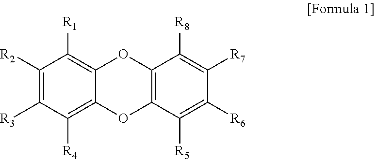
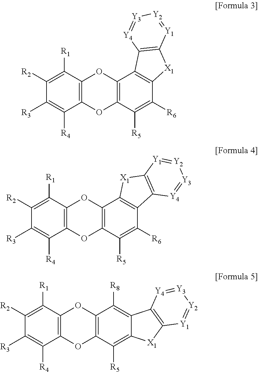
[0027]In the organic compound according to the present disclosure, an indole moiety, a benzothiophene moiety, a benzofuran moiety, or the like is fused with dibenzo[b,e][1,4]dioxine to form a basic skeleton, and the organic compound has a structure in which various substituents are bonded to or fused with the basic skeleton, and is represented by Formula 1.
[0028]In general, the phosphorescent light emitting layer in the organic material layers included in the organic electroluminescent device includes a host and a dopant in order to increase the color purity and the light emitting efficiency. In this case, the host needs to have a higher triplet energy gap than that of the dopant. That is, in order to effectively provide a phosphorescent light emission from the dopant, the lowest excitation state energy of the host needs to be higher than the lowest emission state energy of the dopant. The compound represented by Formula 1 has a wide singlet energy level and a high triplet energy level in which the dibenzo[b,e][1,4] dioxine portion. A specific substituent may be introduced into the indole moiety which is fused with dibenzo[b,e][1,4]dioxine to exhibit a higher energy level than that of the dopant when the compound of Formula 1 is applied as a host of the light emitting layer.
[0029]Further, since the compound represented by Formula 1 has a high triplet energy as described above, it is possible to prevent diffusing (moving) an exciton produced from a light emitting layer to an adjacent electron transport layer or an adjacent hole transport layer. Accordingly, when the compound of Formula 1 is used to form an organic material layer (hereinafter, referred to as a ‘light emitting auxiliary layer’) between a hole transport layer and a light emitting layer or form an organic material layer (hereinafter, referred to as an ‘electron transport auxiliary layer’) between a light emitting layer and an electron transport layer, the diffusion of excitons is prevented by the compound, so that the number of excitons substantially contributing to light emission in the light emitting layer is increased, and thus the light emitting efficiency of the device may be improved, unlike an organic electroluminescent device in the related art, which does not include the light emitting auxiliary layer or the electron transport auxiliary layer.

Problems solved by technology

However, unlike green or red phosphorescent devices, in blue phosphorescent devices, the level of development for the color purity of a dark blue color, a phosphorescent dopant with high efficiency, and a host with a wide energy gap has been so little that commercialization has not even started, and instead, a blue fluorescent device has been used in products.
Due to the high resolution, the light emitting area of the organic EL pixels has decreased, thereby resulting in reduction in the lifetime of the device.
However, since the materials for the organic EL device in the related art have a low glass transition temperature and thus are very poor in thermal stability, the materials fail to reach a level which is satisfactory in terms of a lifetime of an organic EL device, and need to be improved even in terms of light emitting characteristics.

Method used


Image

  • Organic compound and organic electroluminescent element comprising same
  • Organic compound and organic electroluminescent element comprising same
  • Organic compound and organic electroluminescent element comprising same

Examples


preparation example 2

Synthesis of Compounds Inv3 and Inv4

[0125]

Synthesis of 2-(dibenzo[b,e][1,4]dioxin-2-yl)-4,4,5,5-tetramethyl-1,3,2-dioxaborolane

[0126]2-bromodibenzo[b,e][1,4]dioxine (100 g, 0.38 mol), bis(pinacolato)diboron (115.8 g, 0.46 mol), Pd(dppf)Cl2 (31 g, 0.038 mol), and KOAc (111.9 g, 1.14 mol) were put into a flask, 1,4-dioxane (2 L) was added thereto to dissolve the mixture, and then the resulting solution was heated and stirred for 8 hours. After the reaction was terminated, distilled water was added thereto, and an organic layer was extracted with ethyl acetate. The obtained organic layer was dried over Na2SO4, distilled under reduced pressure, and then purified with column chromatography to obtain a compound 2-(dibenzo[b,e][1,4]dioxin-2-yl)-4,4,5,5-tetramethyl-1,3,2-dioxaborolane (73 g, yield 62%).

Synthesis of 2-(5-chloro-2-nitrophenyl)dibenzo[b,e][1,4]dioxine

[0127]The 2-(dibenzo[b,e][1,4]dioxin-2-yl)-4,4,5,5-tetramethyl-1,3,2-dioxaborolane (73 g, 0.235 mol) obtained in , 2-bromo-4-c...

preparation example 3

Synthesis of Compounds Inv5 and Inv6

[0129]

Synthesis of 2-(dibenzo[b,e][1,4]dioxin-2-yl)-4,4,5,5-tetramethyl-1,3,2-dioxaborolane

[0130]2-bromodibenzo[b,e][1,4]dioxine (100 g, 0.38 mol), bis(pinacolato)diboron (115.8 g, 0.46 mol), Pd(dppf)Cl2 (31 g, 0.038 mol), and KOAc (111.9 g, 1.14 mol) were put into a flask, 1,4-dioxane (2 L) was added thereto to dissolve the mixture, and then the resulting solution was heated and stirred for 8 hours. After the reaction was terminated, distilled water was added thereto, and an organic layer was extracted with ethyl acetate. The obtained organic layer was dried over Na2SO4, distilled under reduced pressure, and then purified with column chromatography to obtain a compound 2-(dibenzo[b,e][1,4]dioxin-2-yl)-4,4,5,5-tetramethyl-1,3,2-dioxaborolane (73 g, yield 62%).

Synthesis of 2-(4-chloro-2-nitrophenyl)dibenzo[b,e][1,4]dioxine

[0131]The 2-(dibenzo[b,e][1,4]dioxin-2-yl)-4,4,5,5-tetramethyl-1,3,2-dioxaborolane (73 g, 0.235 mol) obtained in , 1-bromo-4-c...

preparation example 4

Synthesis of Compounds Inv7 and Inv8

[0133]

Synthesis of 2-bromo-7-phenyldibenzo[b,e][1,4]dioxine

[0134]2,7-dibromodibenzo[b,e][1,4]dioxine (137 g, 0.400 mol), phenylboronic acid (49 g, 0.400 mol), and Pd(dppf)Cl2 (23.1 g, 0.02 mol) were put into a flask, a 2 M saturated aqueous solution of Na2CO3 (600 ml) and 1,4-dioxane (2 L) were added thereto to dissolve the mixture, and then the resulting solution was heated and stirred for 8 hours. After the reaction was terminated, distilled water was added thereto, and an organic layer was extracted with ethyl acetate. The obtained organic layer was dried over Na2SO4, distilled under reduced pressure, and then purified with column chromatography to obtain a compound 2-bromo-7-phenyldibenzo[b,e][1,4]dioxine (129 g, yield 95%).

Synthesis of 4,4,5,5-tetramethyl-2-(7-phenyldibenzo[b,e][1,4]dioxin-2-yl)-1,3,2-dioxaborolane

[0135]The 2-bromo-7-phenyldibenzo[b,e][1,4]dioxine (129 g, 0.38 mol) obtained in , bis(pinacolato)diboron (115.8 g, 0.46 mol), P...


PUM


Abstract

The present disclosure relates to a novel organic compound and an organic electroluminescent device comprising the same, and the organic compound of the present disclosure may be used for an organic material layer of the organic electroluminescent device, thereby improving the light emitting efficiency, driving voltage, lifetime, and the like of the organic electroluminescent device.

Description

TECHNICAL FIELD[0001]The present disclosure relates to a novel organic compound and an organic electroluminescent device comprising the same.BACKGROUND ART[0002]Since 1965, studies on an organic electroluminescent (EL) device (hereinafter, simply referred to as an ‘organic EL device’) leading to blue electric light emission using an anthracene single crystal had been continuously conducted, and in 1987, an organic EL device having a two-layer laminated structure including a hole layer (NPB) and a light emitting layer (Alq3) was proposed by Tang. Since then, the organic EL device has been proposed in the form of a multilayer-laminated structure which imparts each characteristic and subdivided function, such as an organic layer which is responsible for injecting and transporting holes, an organic layer which is responsible for injecting and transporting electrons, and an organic layer which induces electroluminescence to occur due to the combination of holes and electrons in the devic...

Claims


Application Information

Patent Timeline
Patent Type & Authority Applications(United States)
IPC IPC(8): H01L51/00C09K11/06C07D491/056
CPCH01L51/0071H01L51/0054H01L51/0061H01L51/006H01L51/0067H01L51/0072H01L51/0074C09K11/06H01L51/5056H01L51/5012H01L51/5072H01L51/0052C09K2211/1007C09K2211/1011C09K2211/1014C09K2211/1033C09K2211/1092H01L51/0068H01L51/0065C09K2211/1088H01L51/0058H01L51/0069C09K2211/1037C09K2211/1044C09K2211/1059C07D491/056C07D493/04C07D495/04H10K85/633H10K85/653H10K85/655H10K85/631H10K85/654H10K85/6576H10K85/6572H10K85/657H10K85/324H10K85/342H10K50/11H10K2101/10H10K50/15C07D319/24C07D491/04H10K50/00H10K85/636H10K50/16H10K85/615H10K85/622H10K85/626H10K85/656
Inventor CHOI, TAE JINPARK, HO-CHEOLBEAK, YOUNGMIKIM, EUNJIN
Owner DOOSAN SOLUS CO LTD
Why Eureka
Try Eureka