Having tested numerous products on the market today that are representative of the kinds of standing platforms available and also evaluated currently existing designs, none have been found that satisfy the optimal
metrics for performance of the disclosed devices detailed herein.
Additionally, over-pronation is a common problem for many standing users.
Normal pronation provides an important shock absorbing function for the human foot, but some users suffer from excessive pronation (colloquially referred to as “flat feet”) in varying degrees, which can create additional fatigue to a user's foot, as well as cause other physical discomforts.
Tired feet (especially feet that are in a less than optimum stance) are a common complaint of many standing users.
Significantly, such dampening characteristics (lower
coefficient of restitution) discourage users from moving because they deaden and do not significantly return the energy that the user puts into the mat.
Prolonged standing without significant movement has been shown by many studies to lower user energy and productivity and to be detrimental to health.
This area is more unstable and less supportive and thereby causes users to rock their feet into the softer area, which encourages users to move more and increases the
health benefits of standing.
Currently, users are generally compelled to choose between an anti-fatigue mat designed to absorb standing pressure underfoot or to instead forgo that in favor of a specialized exercise device that is less suited to serve as an anti-fatigue platform.
Note that the American Society of Testing and Materials (ASTM) standard for Indentation Force Deflection (IFD) is not employed as a metric because it is not well suited to characterize the disclosed devices.
Similarly, the ASTM D2230 standard for
shore durometer
hardness is not utilized because it is also not well suited to characterize the disclosed devices.
Further, none of these standards address the linear quality of the compression modulus over a range of strains for the disclosed devices.
However the ranges may vary with slightly less optimal characteristics, or may vary for highly specific uses.
A mat that cannot support at least its own weight without bending and collapsing before a load is applied does not satisfy this metric because its bending rigidity cannot be measured.
A mat that cannot support at least its own weight without bending and collapsing before a load is applied does not satisfy this metric because its bending rigidity cannot be measured.
A user is generally capable of attaining the lower ranges of strains, but the higher ranges of strains may not be attainable for a given device by some users due to the forces required being beyond their ability or weight.
This bunching has potential to tangle the foot and cause a trip.
Additionally, a mat with a high loaded
friction force presents a
reduced risk that the mat slips out from under a user that is standing or stepping on it, causing a fall
hazard.
A mat with low values of bending rigidity and
flexural rigidity therefore does not provide the same feel or benefit nor does it encourage users to rock and move more during use.
A mat with very high values of bending rigidity and
flexural rigidity is relatively hard / firm and unforgiving and thus lacks the resiliency to provide a responsive surface that encourages the user to move more by giving immediate feedback to the user's movement.
They are not well designed to enhance
exercise activity in a positive manner, but rather to reduce discomfort by absorbing shock to create a low-
impact surface on which individuals may move and shift while standing with lower compressive stress levels exerted on their body.
While this construction helps to absorb, dampen, and neutralize
impact forces when shifting stance or moving from side to side, and also equalize pressure along the bottom of the foot, it does not provide the ideal rebound
metrics for standing that are provided by the disclosed devices falling within the disclosed ranges of the
metrics.
Tested anti-fatigue mats do not provide an immediate
rebound effect or feedback force to a user standing upon them, consequently, the user is not consciously or unconsciously motivated to move more due to the lack of responsiveness and feedback of the currently existing designs.
Additionally, one may decrease the stability of the mat in small progressions by use of the adjustment mechanism to stimulate more micro adjustments by the user in their stance, often occurring unconsciously, which stimulates
blood flow and improves the standing experience and benefits.
As disclosed, current anti-fatigue mats fail to provide the trampoline-like dynamic
surface response of the disclosed devices.
Even firm, high-grade anti-fatigue mats fail to provide the energetic responsiveness of the disclosed devices.
However such a
slow response is not as desirable or healthy for individuals that stand at a
desk and move very little.
A collapsing edge is counterintuitive to such a design.
Unfortunately, the desired bouncy response is degraded at the tapered edge perimeter area, in contrast to the disclosed mat designs, whose linear compression modulus ratio is roughly 0.87.
Typical anti-fatigue mats may angle or taper their edge for a smoother transition to the floor surface, but the protection of the padding provided by these mats is also degraded and lost by this tapering at the edge.
Thus, such a mat is not designed or intended for a user to stand at its edge; nor is the user encouraged to have part of their foot both on and off the mat, as that stance undermines the anti-fatigue purpose of the mat due to the thinner, and therefore less
cushioning, tapered edge.
Such use is not viable with existing anti-fatigue mat designs.
This non-linear curve makes the rebound cycle feel uneven and less comfortable for the user.
While this construction helps to neutralize downward pressure and equalize the pressure points on the foot, it also embodies drawbacks in its current design and use.
It was found during design and testing of products during development of the disclosed devices, that standing for long periods of time on current anti-fatigue mats resulted in negative physical responses with
back discomfort and foot fatigue.
In a large percentage of users, this contributes to poor back posture, discomfort, and foot fatigue.
This then results in an uneven and uncustomary pressure distribution across the foot because the
heel receives a higher pressure or load than the
forefoot, which is counter to what most users have unconsciously trained their bodies to perform.
Further, this problem has not been properly diagnosed or addressed in current anti-fatigue mat designs because these mats were larger and originally designed for use in physically active environments and not for standing in one place for a long period of time with little to no movement.
Also, the problem has not been addressed historically due to ignorance or a lack of interest in improving anti-fatigue mats beyond a generally
horizontal orientation.
This results in the worker standing for long periods of time in a single orientation.
However, none of these methods and habits are necessarily optimum for an office employee using a standing
desk where they spend a majority of their time standing in only one place in front of their personal
workspace, which often has a computer and keyboard.
Traditional mats are compliant and bend easily, and cannot store enough
potential energy to make exercise effective due to their lack of bending rigidity.
This means that the equivalent spring rate of the elastic cord and platform
system is driven by the low spring rate of the platform, which renders it almost useless for exercise.
In this case, the mat deflects excessively, and it is not possible to increase the resistance of a workout because the equivalent spring rate of the
system is still driven by the soft mat even when changing to higher spring rate elastic cords.
Traditional anti-fatigue mats are less suited for the disclosed use as a platform for exercise attachments because they lack the ability to store enough
potential energy in their deflection in the advantageous manner just disclosed.
Additionally, on a wet surface, such as one upon which coffee or other drink has been spilled, the utilization of divots are believed to provide added safety by providing for increased friction due to the need for any liquid to fill the divots before the whole surface can hydroplane and cause a slipping
hazard.
However, when load is applied from above, such as when a user stands on any portion of the mat, the friction is increased by way of more points or area of contact between the mat and the floor such that the mat does not readily slide or move when in a weighted condition, requiring a greater force to overcome the now greater
friction effect that is compounded by the greater load.
But users at these extremes of light or
heavy weight are not the typical adult weight user that utilizes such mats.
One cannot readily flip such a mat on its side or easily
push out of the way when desired.
One great downside of current anti-fatigue mats is that they are relatively difficult to move around.
This poses a challenge in that standing workers also need to sit down during the workday.
Non-stop or excessive standing is not generally recommended, especially in an office environment.
Current mats are not very easy to move or slide around, or reorient to be placed out of the way of the now sitting user.
Additionally, such mats cover enough area such that fitting them under desks can be more challenging.
If wires, outlets, garbage cans, briefcases or other items are stowed under the
desk, then sliding a standard anti-fatigue mat under the desk becomes even more difficult if not impossible.
Current anti-fatigue mats are more difficult and cumbersome to shift and move in this manner.
However, when a worker desires to sit, they often need to move or shift the mat out of the way to better accommodate their chair.
Current anti-fatigue mats, especially the heavier more shock absorbing designs, are more difficult to shift and move than the disclosed devices described herein.
The difficulty and annoyance of moving the mat tends to reduce the frequency of changing between a sitting and standing position to the detriment of the worker
Ironically, the recommendation to switch regularly between standing and sitting during work can exacerbate the chance of injury or strain.
Users risk discomfort and injury whenever they bend over at the
waist to grab the mat with their hands.
Moving current anti-fatigue mats often require
hand manipulation because they are less rigid (more “floppy”), have greater floor friction, and of such a weight that moving with feet are difficult.
Being so effective for the office and work environment does not, however, exclude the disclosed devices from non-office environment related activities.
At first, such a generally vertically oriented or thick edge might be seen as a
tripping hazard in a work environment.
However, the edge is employed in concert with a rigid but lightweight structure.
This differs from the counter force of a traditional and therefore higher friction mat and its lack of rigidity to weight that instead cause a stumble or trip when so struck.
Additionally, the ball's
mass is relatively small and therefore provides little resistance to the
momentum of the impacting foot.
As disclosed, when the device is struck accidently by a foot, it generally slides away, however, it is possible that a fixed barrier lies in its path of deflection, such as a table leg.
Additionally, in embodiments with a curved vertically oriented edge, were a fixed barrier to be encountered by the dislodged mat and the mat not deflected around the barrier, the user's foot has a
high likelihood of deflecting around the top or bottom due to the generally vertically oriented edge's curvature.
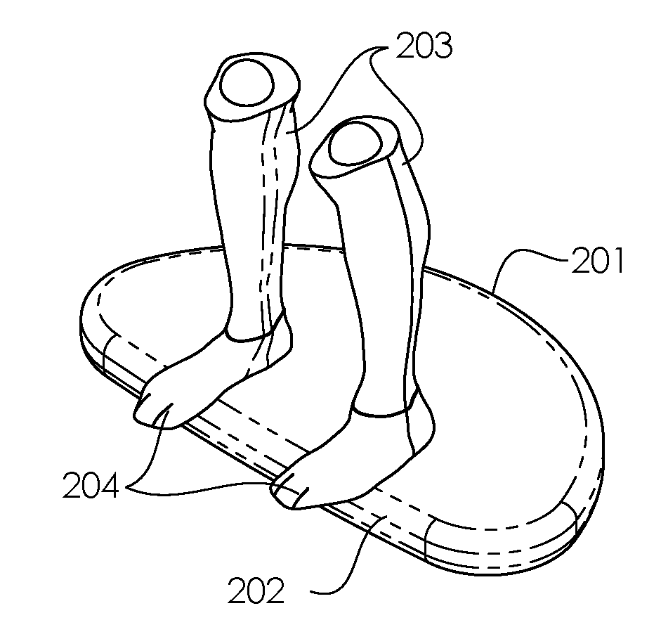
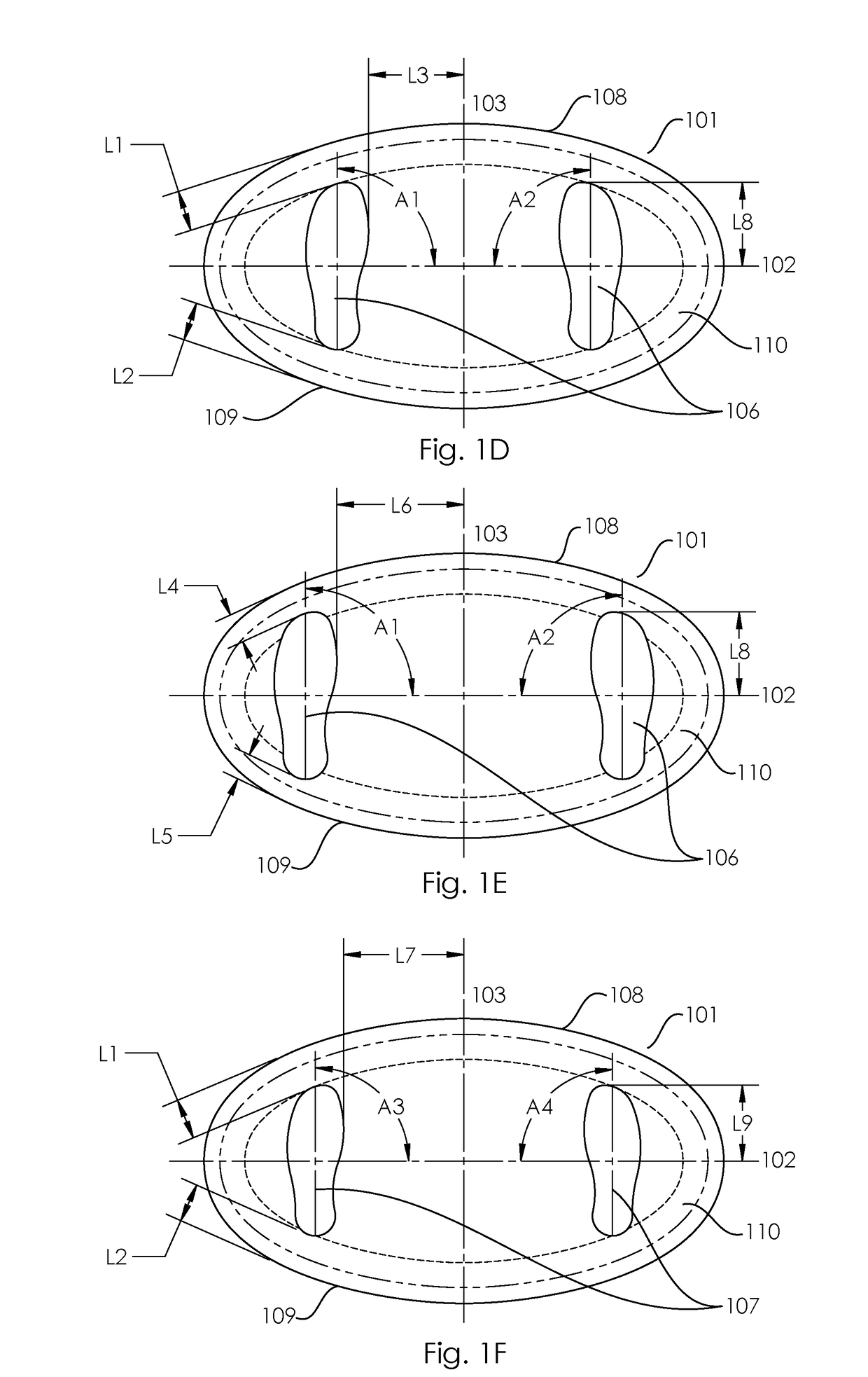
Devices without a flat stable center portion do not give a user the choice to easily avoid a rocking action during their tasks by placing their feet interior to the rocking region and nearer to the center and over the flat stable center portion.
Larger angles tend to result in an uncomfortable stance that begins to feel awkward and unnatural.
A mat that is too long along the major axis does not permit a user to place both their left and right feet in a
fixed position such that they can rock both ends of the mat in succession.
There are several reasons why a user may want to alter the responsiveness of the rocking motion: in one example, a user may be overly sensitive to a highly rockable surface such that a certain level of movement disrupts their concentration while at task during work.

