Fiber laser system

a fiber laser and fiber technology, applied in laser optical devices, laser details, active medium shape and construction, etc., can solve the problems of unstable laser light generation increased conversion efficiency (raman gain) thereof, and malfunctions in each fiber laser, etc., to achieve superior reflection resistance.

Active Publication Date: 2017-06-22
THE FUJIKURA CABLE WORKS LTD
View PDF0 Cites 3 Cited by
  • Summary
  • Abstract
  • Description
  • Claims
  • Application Information

AI Technical Summary

Benefits of technology

[0020]An aspect of the present invention makes it possible to realize a fiber laser system having a reflection resistance property superior to that of conventional techniques.

Problems solved by technology

With the above fiber laser system, there is a risk that light reflected by the processing target object will be reflected back to the fiber laser system and cause a malfunction thereof.
It is known that an increase in the conversion efficiency (Raman gain) thereof corresponds to a greater likelihood of the occurrence of Stokes light vibration.
As a result, laser light generation in each fiber laser becomes unstable, and malfunctions can therefore occur in each fiber laser (see Patent Literature 1).

Method used


Image

  • Fiber laser system
  • Fiber laser system
  • Fiber laser system

Examples


Embodiment Construction

[0025]The following description will discuss an embodiment of the present invention with reference to FIGS. 1 through 3.

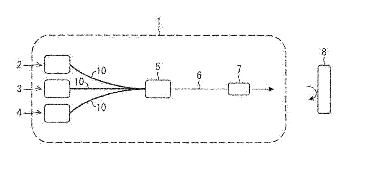
[0026]FIG. 1 schematically illustrates a configuration of a fiber laser system 1 in accordance with Embodiment 1 of the present invention. The fiber laser system 1 includes three (3) (a plurality of) fiber lasers 2 through 4, an output combiner (combiner) 5, a multi-mode fiber (output fiber) 6, an output section 7, and three (3) (a plurality of) optical fibers 10. The fiber laser system 1 processes a processing target object 8 by irradiating it with laser light. Examples of the processing target object 8 include steel materials (mild steel, carbon steel, stainless steel, etc.), non-ferrous materials (aluminum, copper, magnesium, etc.), brittle materials (ceramics, glass, etc.), and other types of materials (plastic, resin, etc.). Of the laser light with which the processing target object 8 is irradiated, approximately 5% to 10% is reflected by the processing target...


PUM


Abstract

A fiber laser system enables an improved reflection resistance property. The fiber laser system includes fiber lasers (2 through 4) each having a laser medium which is an optical fiber made from silica glass. A difference between respective lasing wavelengths of any given two of the fiber lasers is greater than a wavelength equivalent to a half width at half maximum of a peak deriving from a vibration mode of a planar four-membered ring of a Si—O network structure of silica glass.

Description

CROSS-REFERENCE TO RELATED APPLICATIONS[0001]This application is a Continuation of PCT International Application No. PCT / JP2016 / 081722 filed in Japan on Oct. 26, 2016, which claims the benefit of Patent Application No. 2015-214486 filed in Japan on Oct. 30, 2015, the entire contents of which are hereby incorporated by reference.TECHNICAL FIELD[0002]The present invention relates to a fiber laser system including a plurality of fiber lasers.BACKGROUND ART[0003]In recent years, fiber laser systems including (i) a plurality of fiber lasers, (ii) an output combiner for combining laser light outputted by each of the plurality of fiber lasers, and (iii) a output section for outputting laser light from the output combiner to outside the laser system (for example, toward a processing target object) have been attracting attention as a way to achieve an output power of several kW (kilowatts). Light outputted by each of the plurality of fiber lasers propagates through a single-mode fiber or a q...

Claims


Application Information

Patent Timeline
Patent Type & Authority Applications(United States)
IPC IPC(8): H01S3/23H01S3/067
CPCH01S3/067H01S3/2391H01S2301/03H01S3/005G02B6/02
Inventor KASHIWAGI, MASAHIRO
Owner THE FUJIKURA CABLE WORKS LTD
Why Eureka
Try Eureka