Gas turbine engine vane splitter

a technology of gas turbine engines and splitters, which is applied in the direction of machines/engines, stators, liquid fuel engines, etc., can solve the problems of reducing engine efficiency or stability, affecting the efficiency of the engine, and the flow in the region adjacent to the hub wall cannot be so hard worked, so as to reduce the design constraints of the ducts

Inactive Publication Date: 2017-06-29
ROLLS ROYCE PLC
View PDF21 Cites 12 Cited by
  • Summary
  • Abstract
  • Description
  • Claims
  • Application Information

AI Technical Summary

Benefits of technology

[0010]Accordingly, it would be desirable to be able to reduce the design constraints on the ducts within a gas turbine engine.

Problems solved by technology

In turn, this may lead to a longer, heavier engine.
In turn, this may mean that this flow in the region adjacent the hub wall cannot be worked so hard (for example cannot be compressed so much) as the rest of the flow in the passage, for example by the rotor blades.
This may lead to reduced engine efficiency or stability at certain points in the engine operating range.

Method used


Image

  • Gas turbine engine vane splitter
  • Gas turbine engine vane splitter
  • Gas turbine engine vane splitter

Examples


Embodiment Construction

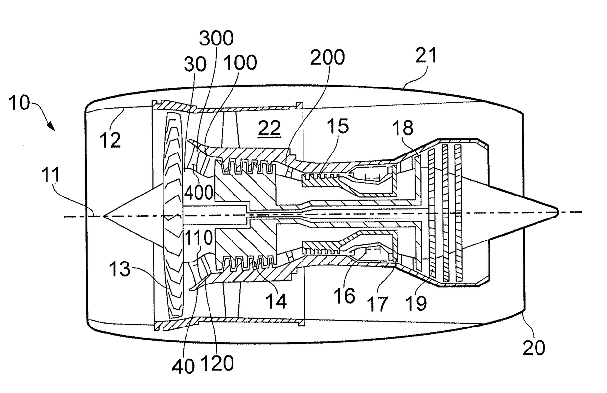
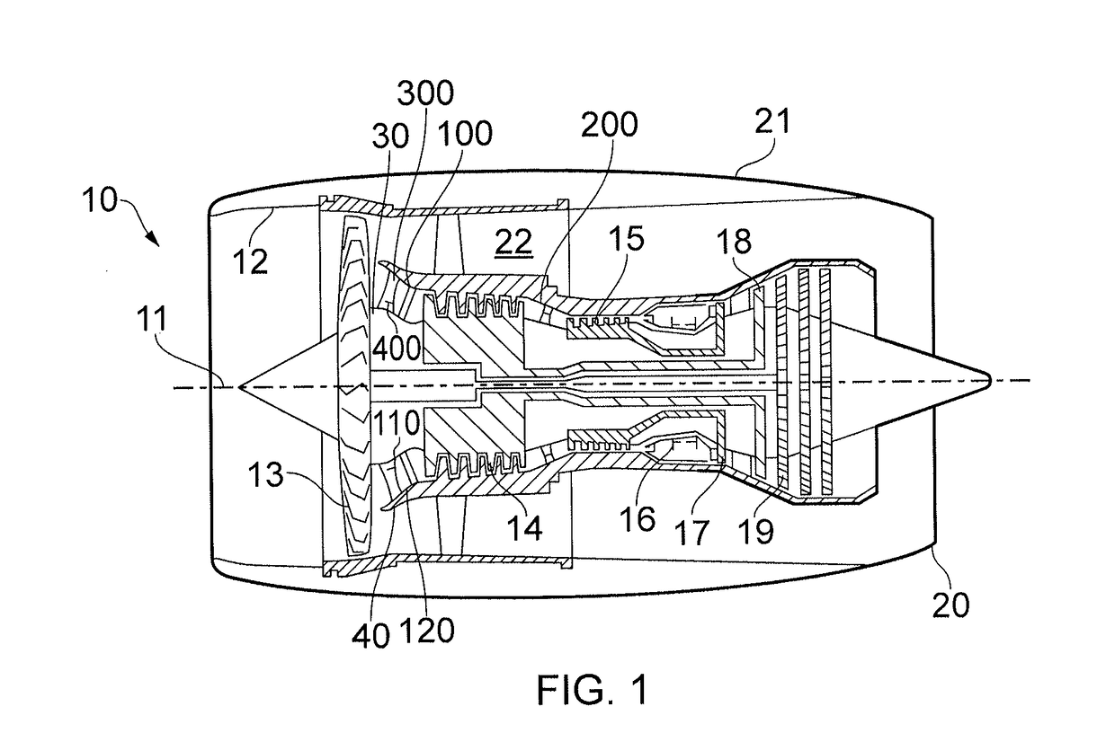
[0064]With reference to FIG. 1, a gas turbine engine is generally indicated at 10, having a principal and rotational axis 11. The engine 10 comprises, in axial flow series, an air intake 12, a propulsive fan 13, an intermediate pressure compressor 14, a high-pressure compressor 15, combustion equipment 16, a high-pressure turbine 17, an intermediate pressure turbine 18, a low-pressure turbine 19 and an exhaust nozzle 20. A nacelle 21 generally surrounds the engine 10 and defines both the intake 12 and the exhaust nozzle 20.

[0065]The gas turbine engine 10 works in the conventional manner so that air entering the intake 12 is accelerated by the fan 13 to produce two air flows: a first air flow into the intermediate pressure compressor 14 and a second air flow which passes through a bypass duct 22 to provide propulsive thrust. The intermediate pressure compressor 14 compresses the air flow directed into it before delivering that air to the high pressure compressor 15 where further comp...


PUM


Abstract

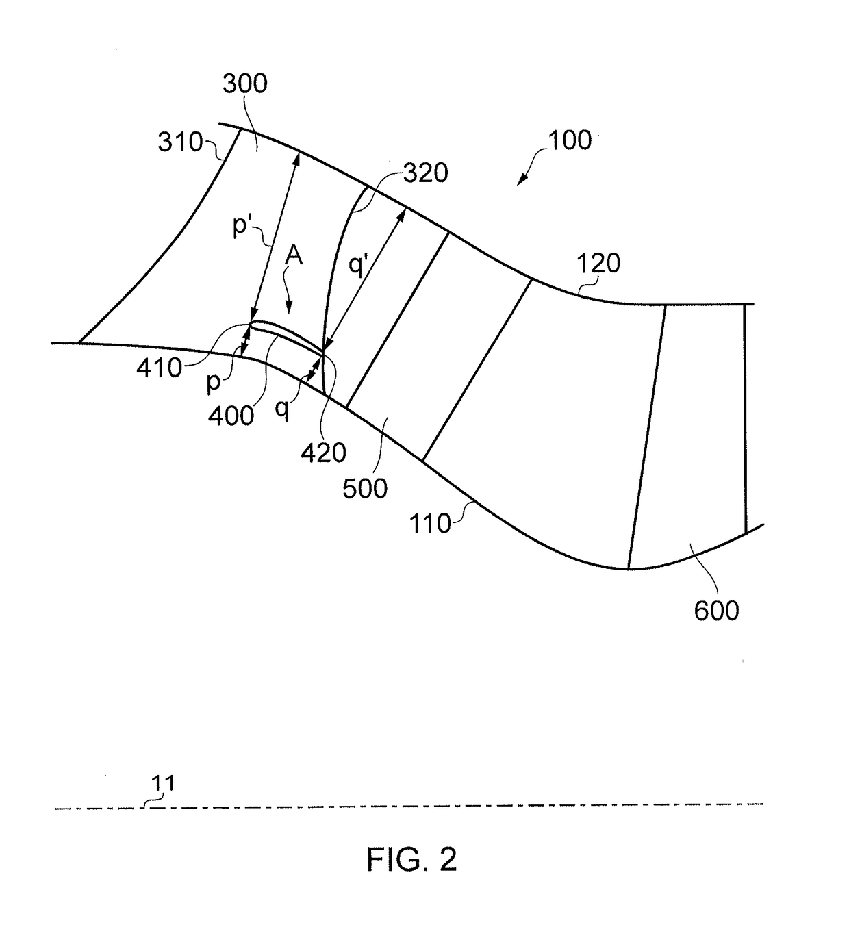
A gas turbine engine duct turns radially inwardly in the downstream direction. The duct includes a plurality of radially extending stator vanes. A generally circumferentially extending splitter vane is provided between two circumferentially neighbouring stator vanes. The splitter vane improves the flow near to the radially inner wall of the duct. This can allow greater design freedom in the duct geometry.

Description

CROSS-REFERENCE TO RELATED APPLICATIONS[0001]This application is based upon and claims the benefit of priority from British Patent Application Number 1522718.4 filed 23 Dec. 2015, the entire contents of which are incorporated by reference.BACKGROUND[0002]1. Field of the Disclosure[0003]The present disclosure relates to a flow splitter, for example a flow splitter in a duct of a gas turbine engine.[0004]2. Description of the Related Art[0005]A gas turbine engine comprises one or more annular flow paths, such as a bypass flow path (in the case of a turbofan gas turbine engine) and a core flow path. The core flow path typically passes through a compressor section, a combustor, and a turbine section. The radius of an annular flow path may vary along the flow path, for example along a generally axial direction.[0006]For example, a typical compressor section comprises one or more regions in which the radius of the annular flow path (for example the mean radius) decreases along the flow di...

Claims


Application Information

Patent Timeline
Patent Type & Authority Applications(United States)
IPC IPC(8): F02K1/82
CPCF02K1/82F01D9/041F01D25/162F01D5/16F05D2250/184F04D29/545
Inventor HARVEY, NEIL W.SPATARO, ROSARIOMILLER, ROBERT J.DAY, IVOR J.
Owner ROLLS ROYCE PLC
Why Eureka
Try Eureka