

Refrigerant distributor, and heat pump device having the refrigerant distributor
- Summary
- Abstract
- Description
- Claims
- Application Information
AI Technical Summary
Benefits of technology
Problems solved by technology
Method used
Image

Examples
embodiment 1
[0040]First, the configuration of a fin and tube type heat exchanger 100 employing a refrigerant distributor 1 of Embodiment 1 will be described.
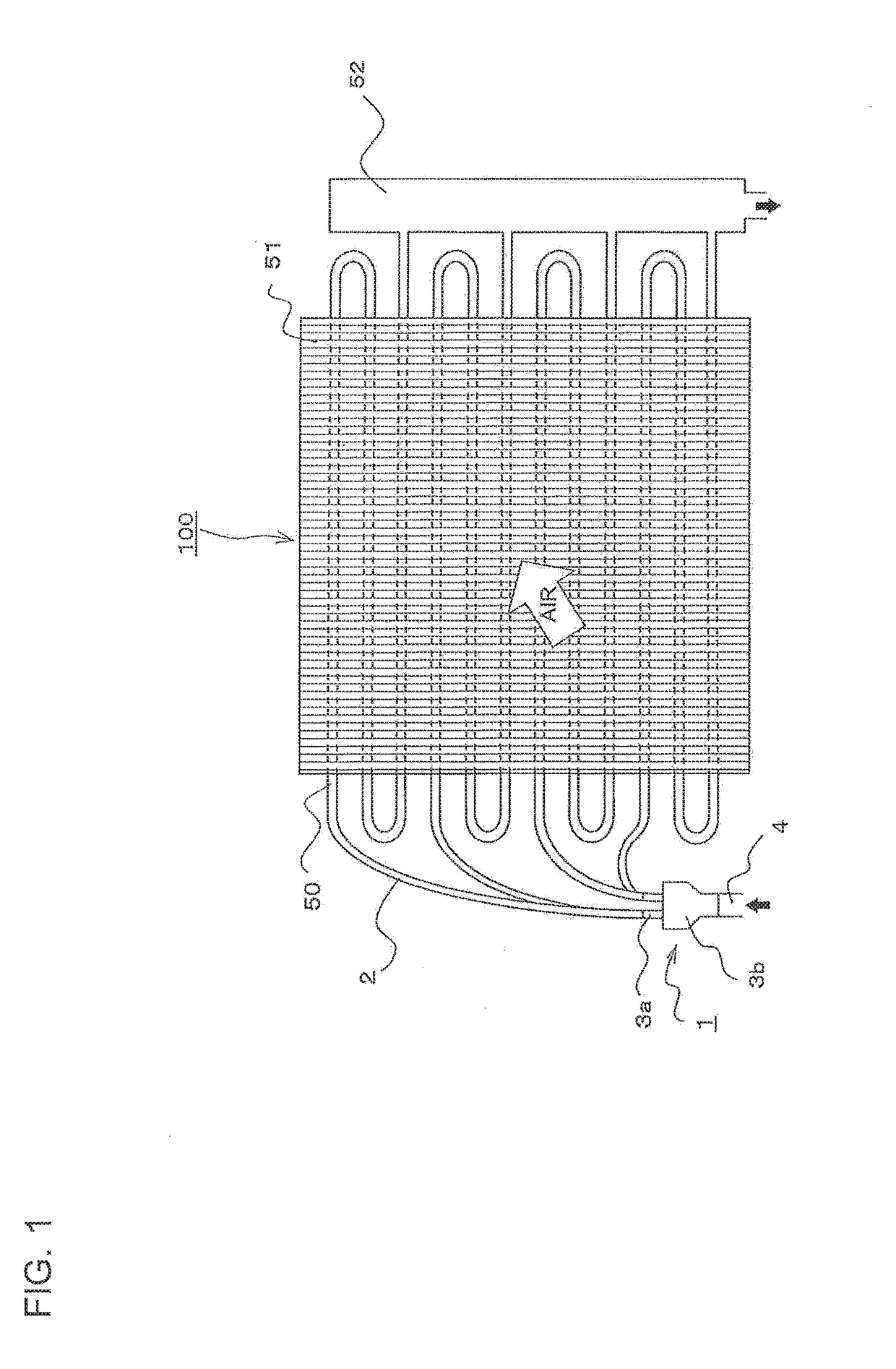
[0041]FIG. 1 shows the configuration of a heat exchanger employing a refrigerant distributor according to Embodiment 1.
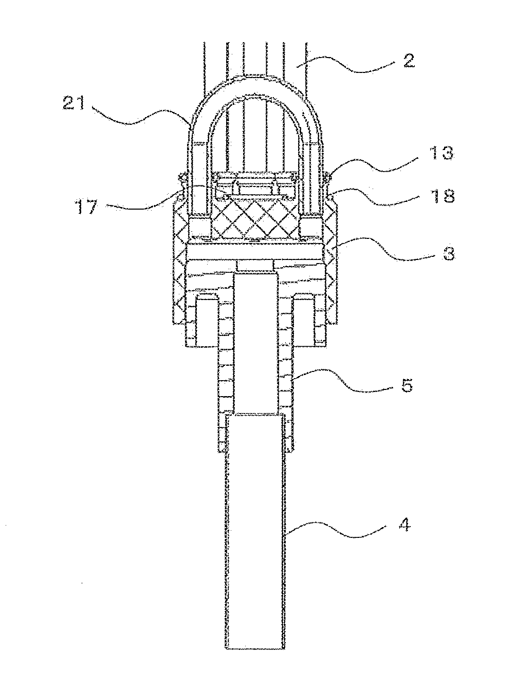
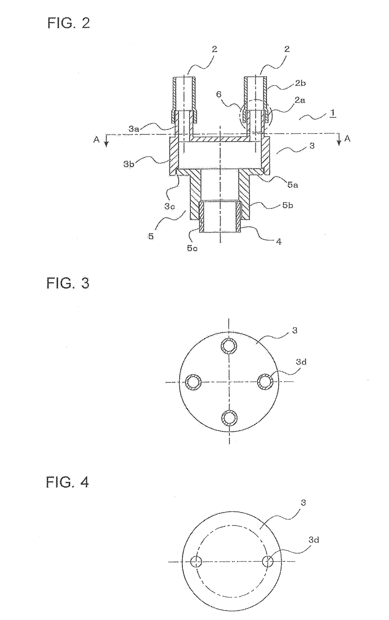
[0042]For example, when the heat exchanger 100 functions as an evaporator, the refrigerant distributor 1 according to Embodiment 1 distributes two-phase refrigerant flowing into the fin and tube type heat exchanger 100 formed by heat transfer tubes 50 and fins 51, and the details will be described later. The two-phase refrigerant flowing through an inflow pipe 4 into the refrigerant distributor 1 branches to each outflow portion 3a in a main body portion 3b of a distributing portion 3, and flows through outflow pipes 2 into the heat transfer tubes 50 forming the paths of the heat exchanger 100.
[0043]The two-phase refrigerant flowing into the heat transfer tubes 50 of the heat exchanger 100 exchanges heat with air passing th...
embodiment 2
[0064]A refrigerant distributor 1 according to Embodiment 2 is the same as the refrigerant distributor according to Embodiment 1 except for the configuration of junctions between the inflow pipe 4 and the inflow portion 5, between the distributing portion 3 and the inflow portion 5, and between the outflow pipes 2 and the outflow portions 3a. So, the difference from the refrigerant distributor 1 according to Embodiment 1 will be mainly described.
[0065]FIG. 7 is a vertical sectional view of the refrigerant distributor 1 according to Embodiment 2.
[0066]The outflow portions 3a are provided with expanded portions 3e in which the upper ends in FIG. 7 are expanded so as to be fitted on the outflow pipes 2 from the outside, and that have a large bore compared to the outflow portions 3a. Therefore, when fitting the outflow pipes 2 into the expanded portions 3e, the outflow pipes 2 are inserted into the expanded portions 3e, the lower ends of the outflow pipes 2 are abutted on stepped portio...
embodiment 3
[0077]A refrigerant distributor 1 according to Embodiment 3 is substantially the same as the refrigerant distributor according to Embodiment 1 except for the configuration of junctions between the outflow pipes 2 and the outflow portions 3a. So, the difference from the refrigerant distributor 1 according to Embodiment 1 will be mainly described.
[0078]FIG. 9 is a vertical sectional view of the refrigerant distributor 1 according to Embodiment 3.
[0079]FIG. 10 is a plan view showing the relative size relationship of a distributing portion 3 according to Embodiment 3.
[0080]FIG. 11 is a vertical sectional view showing the relative size relationship of the distributing portion 3 according to Embodiment 3.
[0081]A main body portion 3b of the distributing portion 3 is formed by cold forging press-like drawing (forging drawing) of a thick plate. The main body portion 3b is formed by a top plate portion 3g and a cylindrical body portion 3h having a cylindrical space 3j therein. A corner portio...
PUM
 Abstract
Description
Claims
Application Information