Combined floormat and body-worn physiological sensors

a technology of physiological sensors and floor mats, applied in the field of sensors, can solve the problems of nullifying the value of such measurements, affecting treatment, and measurement errors, and achieve the effects of convenient measurement of vital signs and hemodynamic parameters, simple form factor, and convenient us

Inactive Publication Date: 2017-07-06
TOSENSE
View PDF7 Cites 5 Cited by
  • Summary
  • Abstract
  • Description
  • Claims
  • Application Information

AI Technical Summary

Benefits of technology

[0028]In view of the foregoing, it would be beneficial to provide a monitoring system that is suitable for home use. Particularly valuable would be a system featuring multiple devices that communicate with each other wirelessly in order to conveniently measure a collection of vital signs and hemodynamic parameter

Problems solved by technology

For TFC deviation in the day-to-day placement of the electrodes can result in measurement errors.
This, in turn, can lead to misinformation (particularly when trends of the measured parameters are to be extracted), thereby nullifying the value of such measurements and thus negatively impacting treatment.
Unfortunately, during a measurement, the lead wires can pull on the electrodes if the device is moved relative to the patient's body, or if the patient ambulates and snags the lead wires on surrounding objects.
Such pulling can be uncomfortable or even painful, particularly where the electrodes are attached to hirsute parts of the body, and this can inhibit patient compliance with long-term monitoring.
Moreover, these actions can degrade or even completely eliminate adhesion of the electrodes to the patient's skin, and in some cases completely destroying the electrodes' ability to sense the physiological signals at various electrode locations.
Chronic elevation of LVEDP causes transudation of fluid from the pulmonary veins into the lungs, resulting in shortness of breath (dyspnea), rapid breathing (tachypnea), and fatigue with exertion due to the mismatch of oxygen delivery and oxygen demand throughout the body.
As CO is compromised, the kidneys respond with decreased filtration capability, thus driving retention of sodium and water and leading to an increase in i

Method used


Image

  • Combined floormat and body-worn physiological sensors
  • Combined floormat and body-worn physiological sensors
  • Combined floormat and body-worn physiological sensors

Examples


Embodiment Construction

1. Product Overview

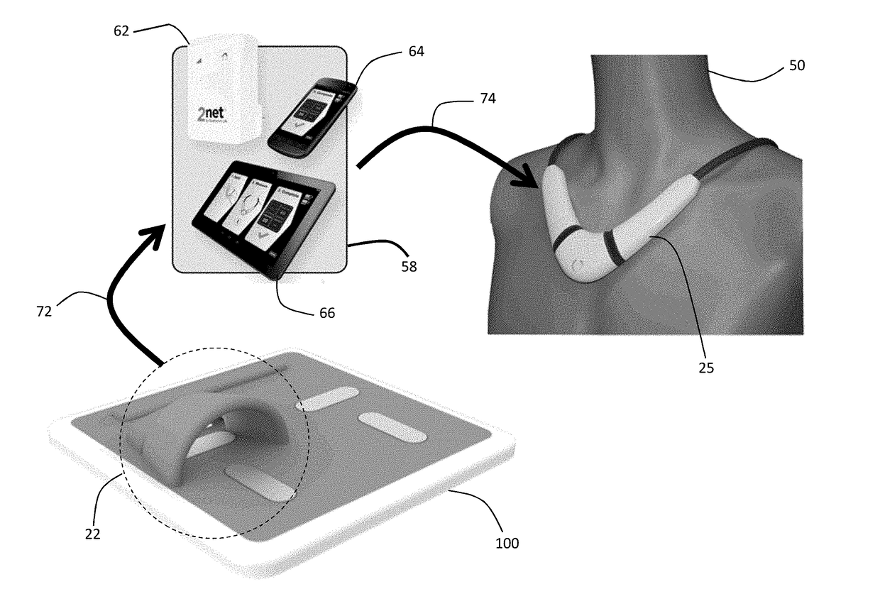
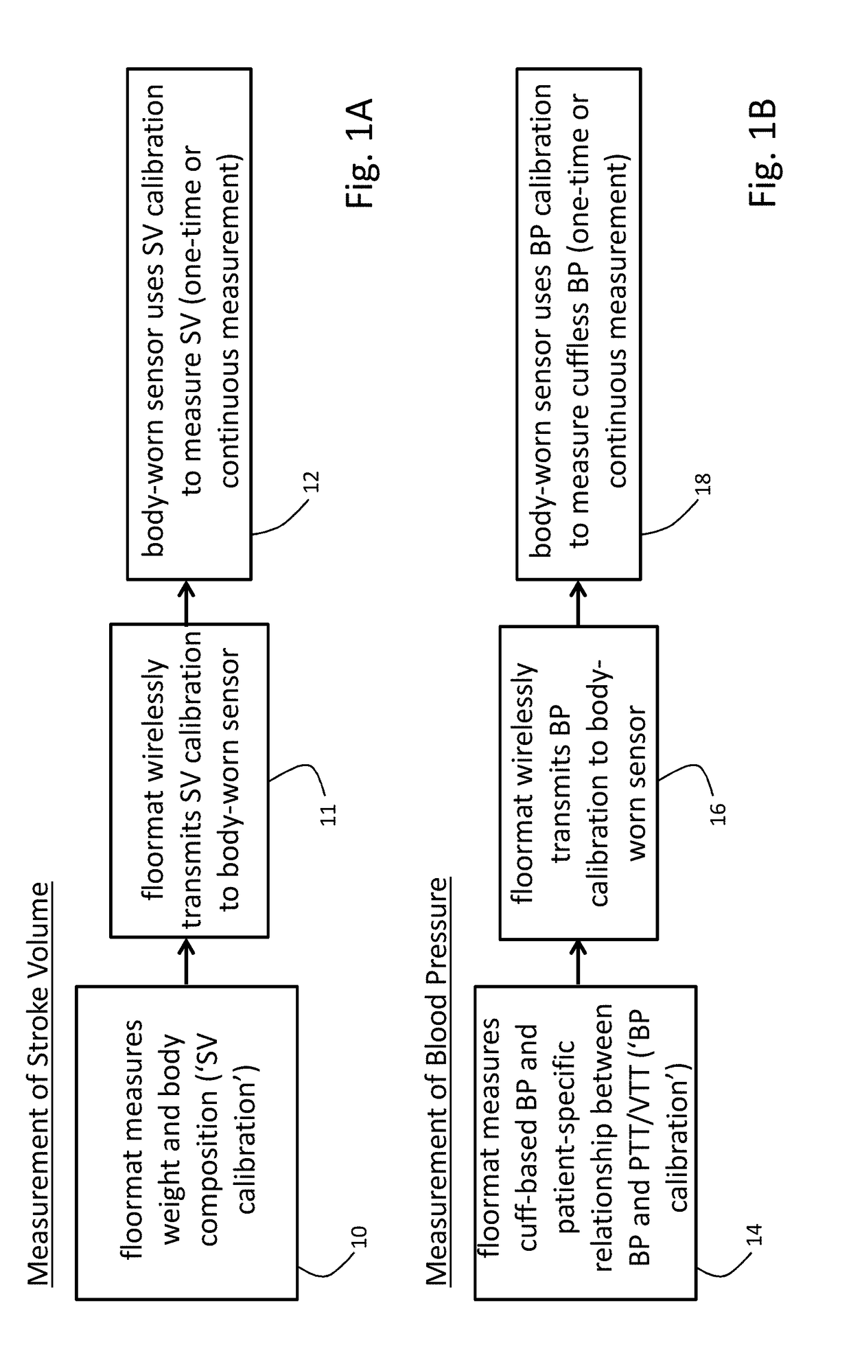
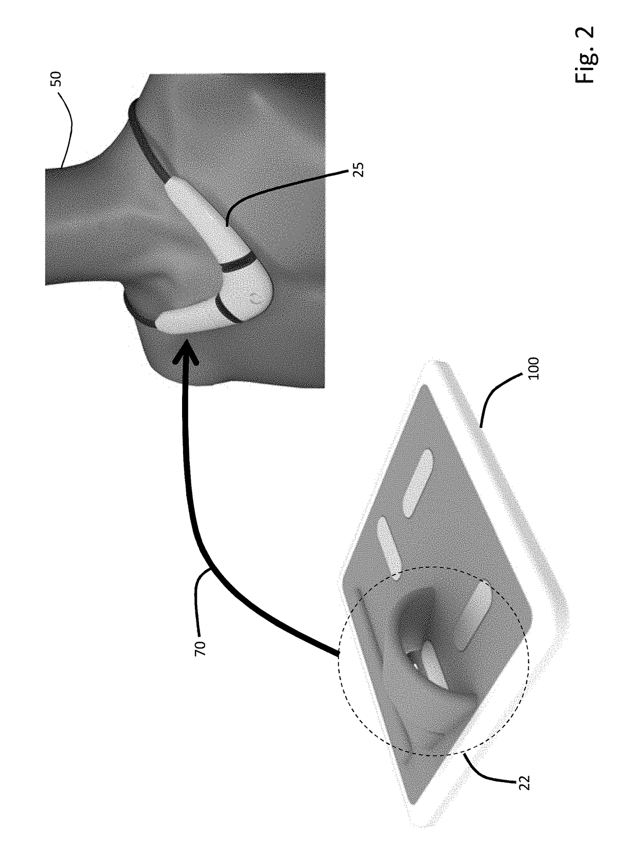
[0089]The invention provides a floormat and body-worn sensor that operate in concert to measure information related to a patient's vital signs, hemodynamic parameters, and body composition. More specifically, the floormat measures parameters used in algorithms on the body-worn sensor for calculating SV and BP. The two systems communicate wirelessly (using, e.g., pair Bluetooth® transceivers) so that the floormat can transmit parameters to the body-worn system, which then processes them as described above.

[0090]In general, the parameters measured by the floormat and then used by algorithms in the body-worn sensor to calculate SV and BP are not available from conventional weight scales. For SV, such parameters (referred to herein as a ‘SV calibration’) include weight and a detailed body composition measured through a combination of bioimpedance and bioreactance. For BP, such parameters (referred to here as a ‘BP calibration’) include initial values of SYS, DIA, MAP,...


PUM


Abstract

The invention provides systems for measuring blood pressure and stroke volume values from a patient. Both systems feature a floormat system and a body-worn sensor working in concert. In aspects, the floormat generates calibrations for both blood pressure and stroke volume measurements. It features a base having a bottom surface configured to rest on or near a substantially horizontal surface, and a top surface configured to receive at least one of the patient's feet. Within the floormat are weight and blood pressure-measuring systems that determine, respectively, the calibrations for stroke volume and blood pressure. Its transmits these parameters to the body-worn sensor, which further processes them, along with other signals, to determine real-time values of blood pressure and stroke volume.

Description

BACKGROUND AND FIELD OF THE INVENTION[0001]1. Field of the Invention[0002]The invention relates to sensors that measure physiological signals from patients, and the use of such sensors.[0003]2. General Background[0004]Known electrical or digital weight scales typically use a load cell, integrated into a Wheatstone Bridge circuit, to measure a patient's weight. In such devices, the load cell exhibits a small, force-dependent resistance changes when the patient steps on the scale. The Wheatstone Bridge features four resistors, at least one of which is part of the load cell, and a measurable / ascertainable voltage change across Bridge varies with the force applied to the load cell. The voltage change thus correlates to the patient's weight. Once the scale is calibrated, the voltage is digitized and processed and ultimately converted into a weight, which is then displayed to the patient.[0005]More advanced electrical or digital weight scales include stainless steel electrodes and associa...

Claims


Application Information

Patent Timeline
IPC IPC(8): A61B5/00A61B5/0205A61B5/1455A61B5/0245A61B5/021A61B5/02A61B5/024
CPCA61B5/6892A61B5/0022A61B5/7275A61B5/4872A61B5/4875A61B5/02007A61B5/02028A61B5/02416A61B5/0245A61B5/02141A61B5/6822A61B5/14551A61B5/0205A61B5/0024A61B5/0537G01G19/50A61B2560/0223
Inventor BANET, MATTHEWDHILLON, MARSHAL SINGHPEDE, SUSAN MEEKSHAYWARD, LAUREN NICOLE MILLERDEPTALA, ARTHURCOCHRAN, JONAS DEAN
Owner TOSENSE
Why Eureka
Try Eureka