Shunt resistor

a resistor and resistor technology, applied in the direction of resistor details, voltage/current isolation, instruments, etc., can solve the problems of inability to achieve a sufficiently high degree of accuracy in measuring the current flowing through the connection conductor, the configuration in the related art may not achieve a sufficiently high degree of accuracy, and the resistance value caused by the conductive adhesive can be restricted. , the effect of increasing the accuracy of measuring the current flowing through the resistive elemen

Active Publication Date: 2017-07-06
DENSO CORP
View PDF6 Cites 5 Cited by
  • Summary
  • Abstract
  • Description
  • Claims
  • Application Information

AI Technical Summary

Benefits of technology

[0014]In the shunt resistor configured as above, the connecting parts are connected to the electrodes as connection targets. The connecting parts and the electrodes are connected via the conductive adhesive, such as solder. The bonding wires in the shunt resistor configured as above are bonded to the bridging part bridging between the two connecting parts. Hence, a resistance value between connection points of the two bonding wires is unsusceptible to conditions of the conductive adhesive, for example, condition of solder, such as a material, an amount, and a location. Consequently, a variance in resistance value caused by the conductive adhesive can be restricted and hence accuracy in measurement of a current flowing through the resistive element can be increased.

Problems solved by technology

Nevertheless, according to the technique of Patent Literature 1, machining is not easy because the current-passing part and the detection parts are provided integrally, and also a degree of freedom for a connected-end member is substantially zero because the detection parts are formed in one shape.
Such a space may possibly make a required size reduction infeasible.
In short, the configuration in the related art may not achieve a sufficiently high degree of accuracy in measurement of a current flowing through the connection conductor.

Method used


Image

  • Shunt resistor
  • Shunt resistor
  • Shunt resistor

Examples


first embodiment

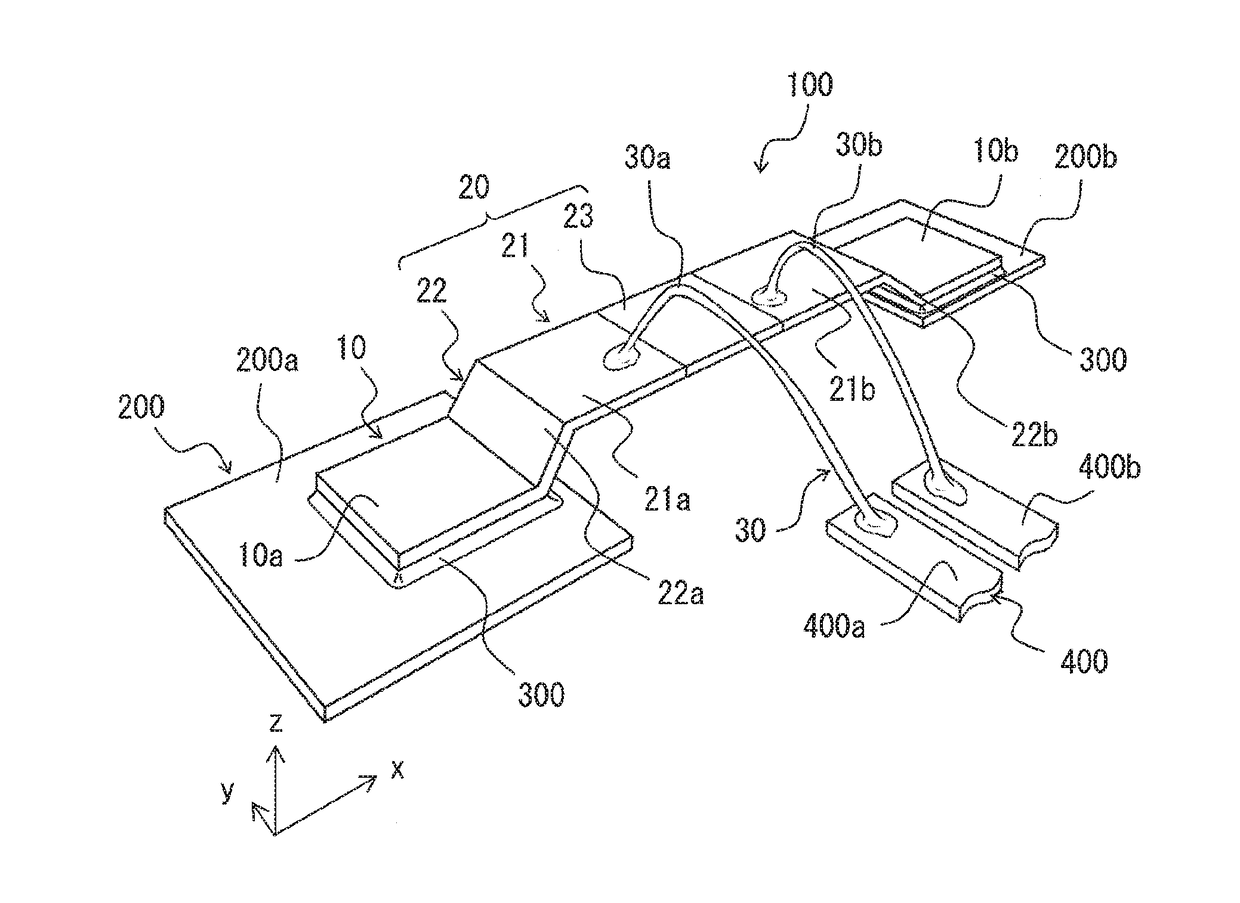
[0025]Firstly, a schematic configuration of a shunt resistor of the present embodiment will be described with reference to FIG. 1.

[0026]As is shown in FIG. 1, a shunt resistor 100 has a surface conforming to the x-y plane and electrically connects two electrodes 200 aligned side by side in the x direction to each other. The shunt resistor 100 described herein connects a first electrode 200a and a second electrode 200b. The electrodes 200 may be, for example, lands provided on a board or a lead frame. In short, a configuration of the electrodes 200 is not particularly limited.

[0027]The shunt resistor 100 includes two connecting parts 10 connected to the electrodes 200 via solders 300 as a conductive adhesive and a bridging part 20 bridging between the two connecting parts 10. The bridging part 20 has a main part 21, an intermediate part 22, and a resistive element 23. The shunt resistor 100 also includes bonding wires 30 used to detect a current value of a current flowing through the...

second embodiment

[0043]The first embodiment above has described the bonding wires 30 as to the bonding positions in detail. In the present embodiment, attention is paid to routing of bonding wires 30.

[0044]As is shown in FIG. 5, two bonding wires 30, namely, the first wire 30a and the second wire 30b, in the shunt resistor 100 of the present embodiment are extracted substantially parallel to an extending direction of the bridging part 20 (an x direction in FIG. 5) to substantially a same direction. Herein, “to a same direction” means that both of the first wire 30a and the second wire 30b are extracted toward a left side on a sheet surface of FIG. 5. That is to say, the first wire 30a and the second wire 30b are extended in the x direction and extracted side by side in a y direction. The present embodiment is of a same configuration as the first embodiment above except for routing of the bonding wires 30.

[0045]According to the configuration as above, a distance between the first wire 30a and the sec...


PUM


Abstract

A shunt resistor, at least a part of which has a resistive element with pre-set resistivity, is configured to bridge between two electrodes and detect a current value of a current flowing between the electrodes by detecting a voltage drop in the resistive element. The shunt resistor includes two connecting parts affixed to the electrodes via a conductive adhesive, respectively, and the connecting parts electrically connected to the affixed electrodes, a bridging part bridging between the connecting parts by being extended from one of the connecting parts to the other one of the connecting parts, and two bonding wires used to detect a voltage drop in the resistive element. The bonding wires are bonded to the bridging part.

Description

CROSS REFERENCE TO RELATED APPLICATION[0001]This application is based on Japanese Patent Application No. 2014-179482 filed on Sep. 3, 2014, the disclosure of which is incorporated herein by reference.TECHNICAL FIELD[0002]The present disclosure relates to a shunt resistor to which bonding wires used to detect a current value flowing between electrodes are connected.BACKGROUND ART[0003]A current value is measured by using a shunt resistor according to a resistance value of a resistive element forming the shunt resistor and a potential difference across the shunt resistor.[0004]A current detection resistor described in Patent Literature 1 includes a current-passing part through which a current flows and detection parts protruding from the current-passing part. The detection parts are provided integrally with the current-passing part and detect a current value according to a resistance value of the current-passing part and a potential difference between two detection parts.[0005]A semic...

Claims


Application Information

Patent Timeline
Patent Type & Authority Applications(United States)
IPC IPC(8): G01R15/14
CPCG01R15/146H01C13/00H01C1/014H01C1/14H01L2224/40245H01L2224/48091H01L2224/48465G01R1/203H01L2924/00014G01R31/364
Inventor KAWAMOTO, IPPEI
Owner DENSO CORP
Why Eureka
Try Eureka