

Method of making an electrode
- Summary
- Abstract
- Description
- Claims
- Application Information
AI Technical Summary
Benefits of technology
Problems solved by technology
Method used
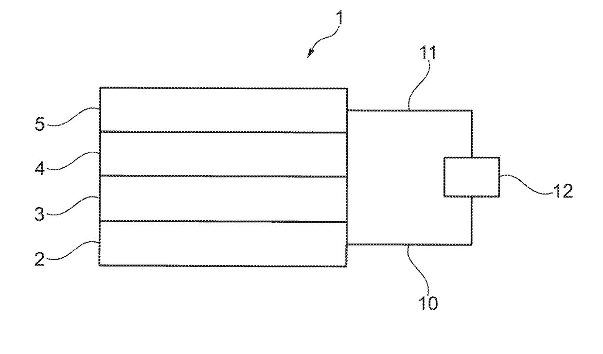
Image

Examples
example 1
Rinse Test Using Hydrocarbon Solvents
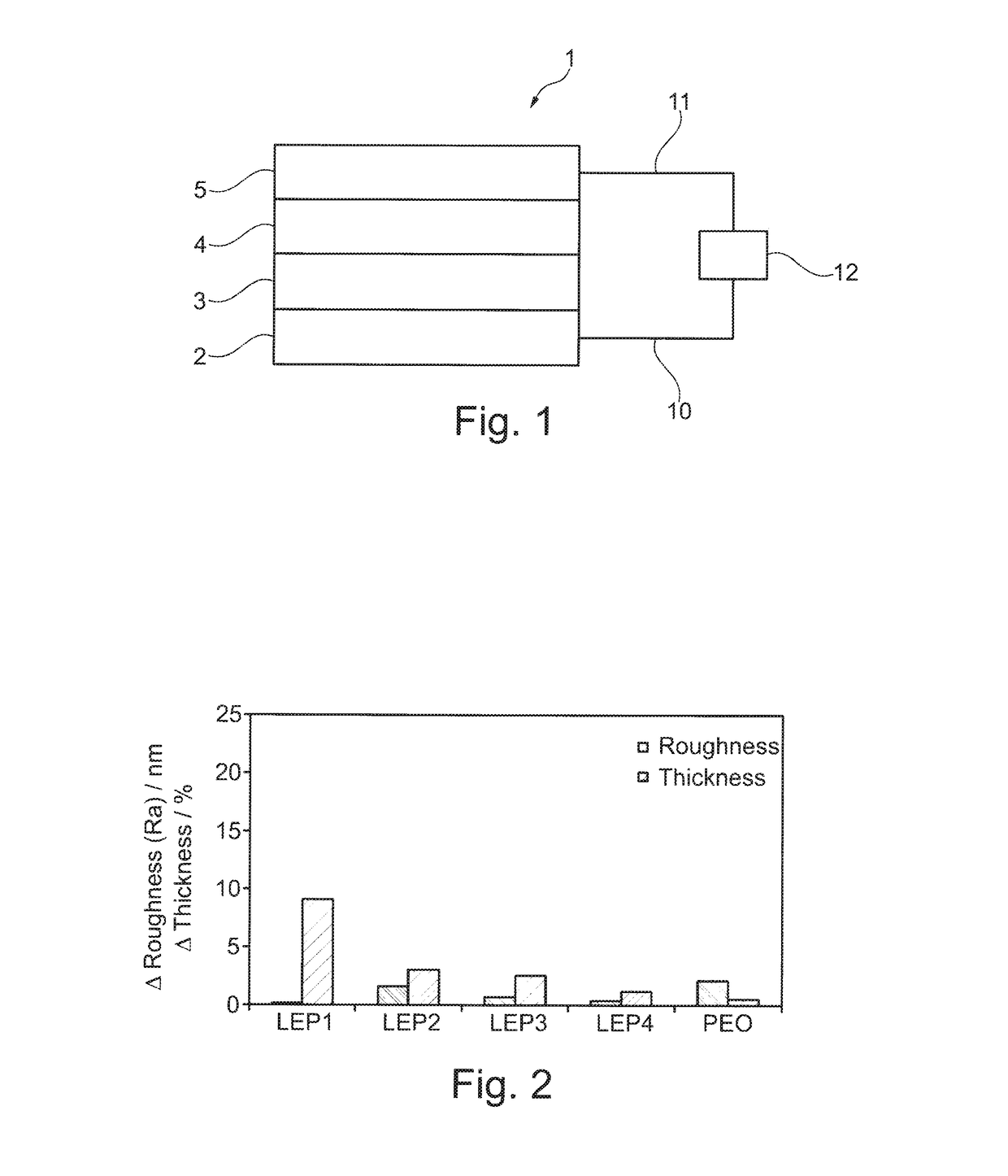
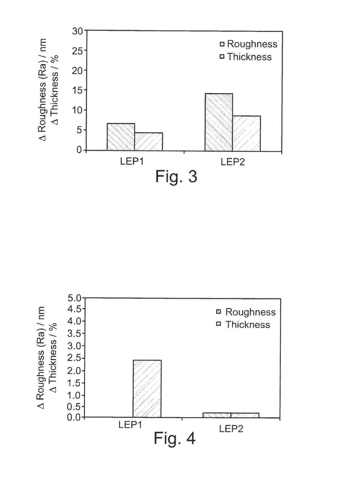
[0218]A surface of a light emitting polymer was prepared as described above. The surface was scored and treated with hydrocarbon solvents according to the rinse test method detailed above. The change in roughness and change in thickness of the scores on the tested surface are summarised in table 2 below. The results are also shown in FIGS. 2-4.
TABLE 2LEP1LEP2LEP3LEP4100k PEORoughness Change on Rinse and Dry / nm1,1′-Bicyclohexyl0.21.60.70.42.1Decalin6.714.3Undecane00.2Thickness Remaining on Rinse and Dry / %1,1′-Bicyclohexyl90.997.097.598.899.5DecalinUndecaneThickness Lost on Rinse and Dry / %1,1′-Bicyclohexyl9.13.02.51.20.5Decalin4.58.8Undecane2.40.2
[0219]The results show that the hydrocarbon solvents tested caused little or no roughening or modification to any of the LEP or PEO polymer surfaces when compared to the conventional solvents. The results demonstrate that these solvents would be useful in screen printable inks for LEC and OLED devices as t...
example 2
Visual Test Using Hydrocarbon Solvents
[0223]Compatibiliser DBE-821 and THPPF6 were separately treated with hydrocarbon solvents and with conventional solvents according to the visual test method detailed above. Any change in solubility was assessed visually as shown in table 5 below.
TABLE 5Salt solubiltySalt solubilityDBE-821Solventcold + stirringat 80° C. + stirringmiscibilityBicycohexylTurbidTurbidForms micellessuspensionsuspensionDoes notbut notbut notdissolvedissolveddissolvedUndecaneDoes notDoes notDoes notdissolvedissolvedissolveTerpineolDissolvesDissolvesTwo phasesCarbitol acetateDissolvesDissolvesDissolvesγ-ButyrolactoneDissolvesDissolvesDissolvesEthylene glycolDoes notTurbidForms micellesdissolvesuspensionDoes notbut notdissolvedissolved
[0224]The results show that hydrocarbon solvents do not dissolve the salts or the DBE-821 compatibiliser upon mixing, stirring and heating. The results show that, whilst ethylene glycol did not dissolve the salts, the effect of the remaining...
PUM
| Property | Measurement | Unit |
|---|---|---|
| Pressure | aaaaa | aaaaa |
| Boiling point | aaaaa | aaaaa |
| Boiling point | aaaaa | aaaaa |
Abstract
Description
Claims
Application Information