Additive layer manufacturing methods

a manufacturing method and additive layer technology, applied in the direction of additive manufacturing processes, manufacturing tools, turbines, etc., can solve the problems of mechanical deficiencies in alm manufactured components, propagation of cracks within components, and limited control of heating and cooling cycles in many known alm technologies, so as to reduce residual stress build-up and achieve more equi-axe grain structure

Inactive Publication Date: 2017-07-13
ROLLS ROYCE PLC
View PDF74 Cites 23 Cited by
  • Summary
  • Abstract
  • Description
  • Claims
  • Application Information

AI Technical Summary

Benefits of technology

[0016]With knowledge of the material of the substrate powder and geometry of the workpiece to be produced, the controller can be pre-programmed to control the heating and / or cooling rate of the substrate so as to reduce residual stress build up in the region of the melt pool and provide a more equi-axe grain structure in the finished workpiece. To achieve this, the second energy beam may be scanned at varying speeds and profiles to optimise cooling as the shape, cross section or the like of the workpiece defined by the path of the first energy beam changes.

Problems solved by technology

Control of heating and cooling cycles in many known ALM technologies is limited.
For example, mechanical deficiencies in an ALM manufactured component can arise when residual stresses result from rapid cooling rates in the heated powder.
In high temperature alloys, these residual stresses can result in propagation of cracks within the component during subsequent heat treatments and / or when in use in a high temperature application.

Method used


Image

  • Additive layer manufacturing methods
  • Additive layer manufacturing methods
  • Additive layer manufacturing methods

Examples


Embodiment Construction

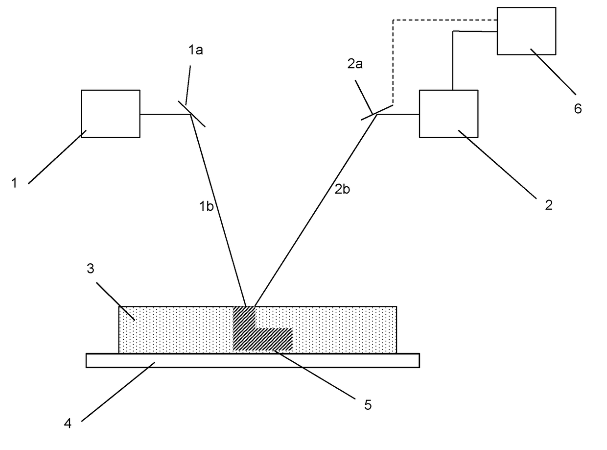
[0039]As can be seen in FIG. 1, an apparatus suitable for performing the ALM process of the invention comprises a first energy beam source 1 with associated optics la for controlling the characteristics of an energy beam 1b emitted by the source 1. Also provided is a second energy beam source 2 with associated optics 2a for controlling the characteristics of an energy beam 2b emitted by the source 2. Both beams 1b, 2b are focused on a bed 3 of a powdered substrate which is provided in sequential layers onto a plate 4. The first energy beam 1b is configured to locally melt powder in the bed 3 which, as it cools, consolidates to form a workpiece 5. The second energy beam 2b is configured to heat powder in the locality of the powder melted by the first energy beam 1b whereby to control the rate of cooling of the melted powder and powder adjacent thereto.

[0040]Movement of the first energy beam 1b is controlled using prior known methods. For example, scanning optics could be used and who...


PUM

PropertyMeasurementUnit
poweraaaaaaaaaa
constant velocityaaaaaaaaaa
distancesaaaaaaaaaa

Abstract

An apparatus and method for performing an ALM process is described. A first energy beam source (1) provides an energy beam (1b) which selectively melts a substrate powder (3) into a melt pool. A second energy beam source (2) provides an energy beam (2b) to heat condition substrate powder proximate to the melt pool. The path of the second energy beam (2b) is controlled by a controller (6) to oscillate independently of the path followed by the first energy beam (1b). The method may be applied to control and optimise heating and cooling rates of the sintered substrate during the ALM process enabling its microstructure to be controlled to suit the end use of the product and reduce the occurrence of residual stresses and consequent crack propagation.

Description

FIELD OF THE INVENTION[0001]The invention relates to the manufacture of components using additive layer manufacturing methods. In particular, the invention provides novel methods which result in improved fracture resistance of the finished component.BACKGROUND OF THE INVENTION[0002]Additive layer manufacturing (ALM) methods are known. In these methods a component is built up layer by layer until the 3D component is defined. In some ALM methods, the layers are laid down from a continuous extrusion of material. In other methods, layers are created by selective treatment of layers within a mass of particulate material, the treatment causing cohesion of selected regions of particulates into a solid mass. In other methods, a liquid mass is selectively treated to produce solid layers. Specific examples of ALM methods include (without limitation); electron beam melting (EBM), direct laser deposition (DLD), laser engineered net shaping (LNS), selective laser melting (SLM), direct metal lase...

Claims


Application Information

Patent Timeline
Patent Type & Authority Applications(United States)
IPC IPC(8): B23K26/342B23K26/064B33Y80/00B33Y10/00B33Y30/00B23K26/03B23K26/06
CPCB23K26/342B23K26/034B23K26/064B23K26/0608B23K2203/52B33Y30/00B33Y80/00B23K2201/001B23K2203/02B33Y10/00B22F5/009B22F5/04B33Y50/02B29C64/153B23K2101/001B23K2103/02B23K2103/52B29C64/277B29C64/268Y02P10/25B22F12/41B22F10/362B22F12/44B22F12/13B22F10/364B22F12/46B22F10/36B22F10/28B22F12/90B22F12/45
Inventor GARRY, IAN M.GRAFTON-REED, CLIVE
Owner ROLLS ROYCE PLC
Why Eureka
Try Eureka