
Method for manufacturing machine components by additive manufacturing

a technology of additive manufacturing and component manufacturing, which is applied in the direction of machines/engines, blade accessories, metal-working apparatuses, etc., can solve the problems of high cost and non-flexible manufacturing process of sintering, and achieve the effect of improving creep resistance, increasing component creep resistance, and avoiding adverse effects on fragility

Active Publication Date: 2017-07-27
BAKER HUGHES INC +1
View PDF6 Cites 24 Cited by
  • Summary
  • Abstract
  • Description
  • Claims
  • Application Information

AI Technical Summary

Benefits of technology

The patent describes a compound called a strengthening dispersor that improves the strength of high-temperature components made through a process called additive manufacturing. The strengthening dispersor is a powder that is added to the raw material mix, which helps to disperse the powder and improve its strength. This results in better performance of the final component made through the manufacturing process. The use of controlled atmosphere or vacuum conditions during additive manufacturing prevents any chemical changes to the strengthening dispersor and ensures its uniform distribution throughout the final component.

Problems solved by technology

Sintering is an expensive and non-flexible manufacturing process.

Method used


Image

  • Method for manufacturing machine components by additive manufacturing
  • Method for manufacturing machine components by additive manufacturing
  • Method for manufacturing machine components by additive manufacturing

Examples


Embodiment Construction

[0020]Reference throughout the specification to “one embodiment” or “an embodiment” or “some embodiments” means that the particular feature, structure or characteristic described in connection with an embodiment is included in at least one embodiment of the subject matter disclosed. Thus, the appearance of the phrase “in one embodiment” or “in an embodiment” or “in some embodiments” in various places throughout the specification is not necessarily referring to the same embodiment(s). Further, the particular features, structures or characteristics may be combined in any suitable manner in one or more embodiments.

[0021]The modifier “about” used in connection with a quantity is inclusive of the stated value and has the meaning dictated by the context (e.g., includes the tolerance ranges associated with measurement of the particular quantity).

[0022]In the following description reference will be made to manufacturing of turbomachine components. It shall however be understood that the met...


PUM

PropertyMeasurementUnit
Grain sizeaaaaaaaaaa

Abstract

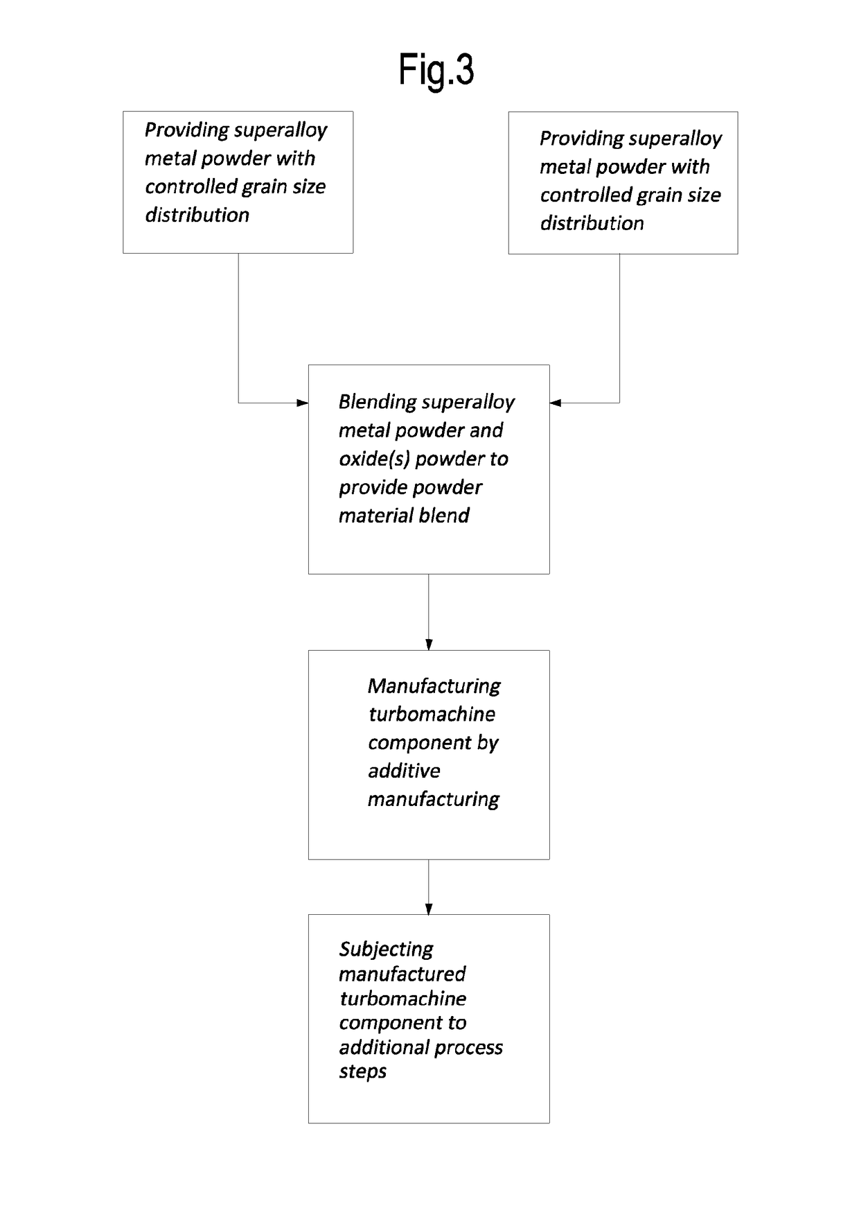
A method for manufacturing a machine component made of metal-based material is described. The method comprises the steps of: providing a powder blend comprising at least one metal-containing powder material and at least one strengthening dispersor in powder form, wherein the strengthening dispersor in powder form has an average grain size less than an average grain size of the metal-containing powder material; and forming the machine component by an additive manufacturing process using the powder blend.

Description

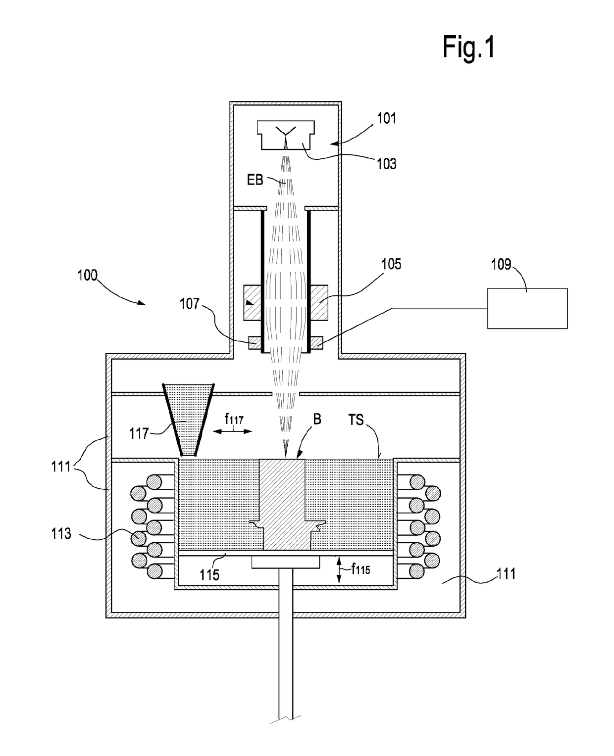
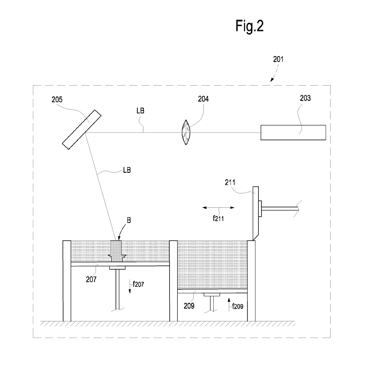
BACKGROUND[0001]The present disclosure relates to the manufacturing of machine components, in particular machine components which are subject to high temperature operating conditions, such as components of internal combustion engines and turbomachines, e.g. but not limited to gas turbines. More specifically, exemplary embodiments of the subject matter disclosed herein relate to the manufacturing of turbomachine components using high-temperature superalloy-based materials, such as but not limited to turbine rotary and stationary blades or buckles, turbine nozzles, turbine impellers.[0002]Use of Oxide Dispersion Strengthened (ODS) superalloys as suitable materials for manufacturing machine components subject to high temperature fatigue cycles is known (D. M. Elzey et al, “Oxide Dispersion Strengthened Superalloys: the Role of Grain Structure and Dispersion During High Temperature Low Cycle Fatigue”, published in Superalloys 1988, The Metallurgical Society, 1988, pages 595-604). These ...

Claims


Application Information

Patent Timeline
IPC IPC(8): B22F1/00B33Y40/00B33Y70/00B33Y80/00B22F3/105B22F3/15B22F3/24B23K26/342B23K26/70B23K26/00C22C19/07C22C19/05C22C27/04C22C27/02C22C32/00B33Y10/00
CPCB22F1/0018F05D2300/175B33Y40/00B33Y70/00B33Y80/00B22F3/1055B22F3/15B22F3/24B23K26/342B23K26/70B23K26/0006C22C19/07C22C19/057C22C19/056C22C27/04C22C27/02C22C32/0005B22F2003/248B22F2302/45B23K2201/001B23K2203/08B23K2203/02F01D5/28F01D9/02F05D2230/233F05D2230/234F05D2230/22B33Y10/00C22C32/001B22F10/00B22F10/32B22F10/34B22F10/28B22F10/64B22F12/49B22F10/368B33Y70/10B33Y40/20B23K2101/001B23K2103/02B23K2103/08Y02P10/25C22C32/0026C22C33/0261C22C33/0285B22F9/082B22F9/14B22F2999/00B22F2202/13B22F2202/07B22F3/105C22C32/00F01D5/00
Inventor GIOVANNETTI, IACOPOTOZZI, PIERLUIGIGIANNOZZI, MASSIMO
Owner BAKER HUGHES INC
Learn More