
Mass spectrometer

a mass spectrometer and mass spectrometer technology, applied in the field of mass spectrometers, can solve the problems of insufficient needle insertion into the hole in the holder, inability to completely prevent contamination, and falling off the holder, so as to reduce workload and waste measurement time

Inactive Publication Date: 2017-08-17
SHIMADZU CORP
View PDF14 Cites 18 Cited by
  • Summary
  • Abstract
  • Description
  • Claims
  • Application Information

AI Technical Summary

Benefits of technology

The present invention is a mass spectrometer that can detect when the probe is attached in an improper way or when the operator forgets to attach a new probe. This prevents the measurement from being performed using an improperly attached probe, which could waste time or lead to the degradation of the sample. Additionally, the mass spectrometer automatically determines the precision of the probe attachment, reducing the workload on the operator. These technical effects prevent the measurement from being wasteful and improve the accuracy and efficiency of the mass spectrometer.

Problems solved by technology

The latter requires a complex system and yet does not guarantee that the contamination can be completely prevented by the cleaning.
Since the needle is extremely thin and small, it is possible that the needle is insufficiently inserted into the hole in the holder and eventually falls off the holder during the measurement.
Another possible situation is that the operator carelessly initiates a measurement while omitting to attach a new probe after having removed the used one from the holder.
If the probe is improperly attached to the holder or detached from it, the measurement cannot yield a correct result, and the measurement time is wasted.
Additionally, if the target of the measurement is a substance sampled from a living organism, the substance will undergo degradation or denaturation with the passage of time after the sampling.
Therefore, if an unnecessary amount of time is consumed in the measurement due to the aforementioned factor, the sample may be no longer usable when the measurement is once more attempted from the beginning.

Method used


Image

  • Mass spectrometer
  • Mass spectrometer
  • Mass spectrometer

Examples


Embodiment Construction

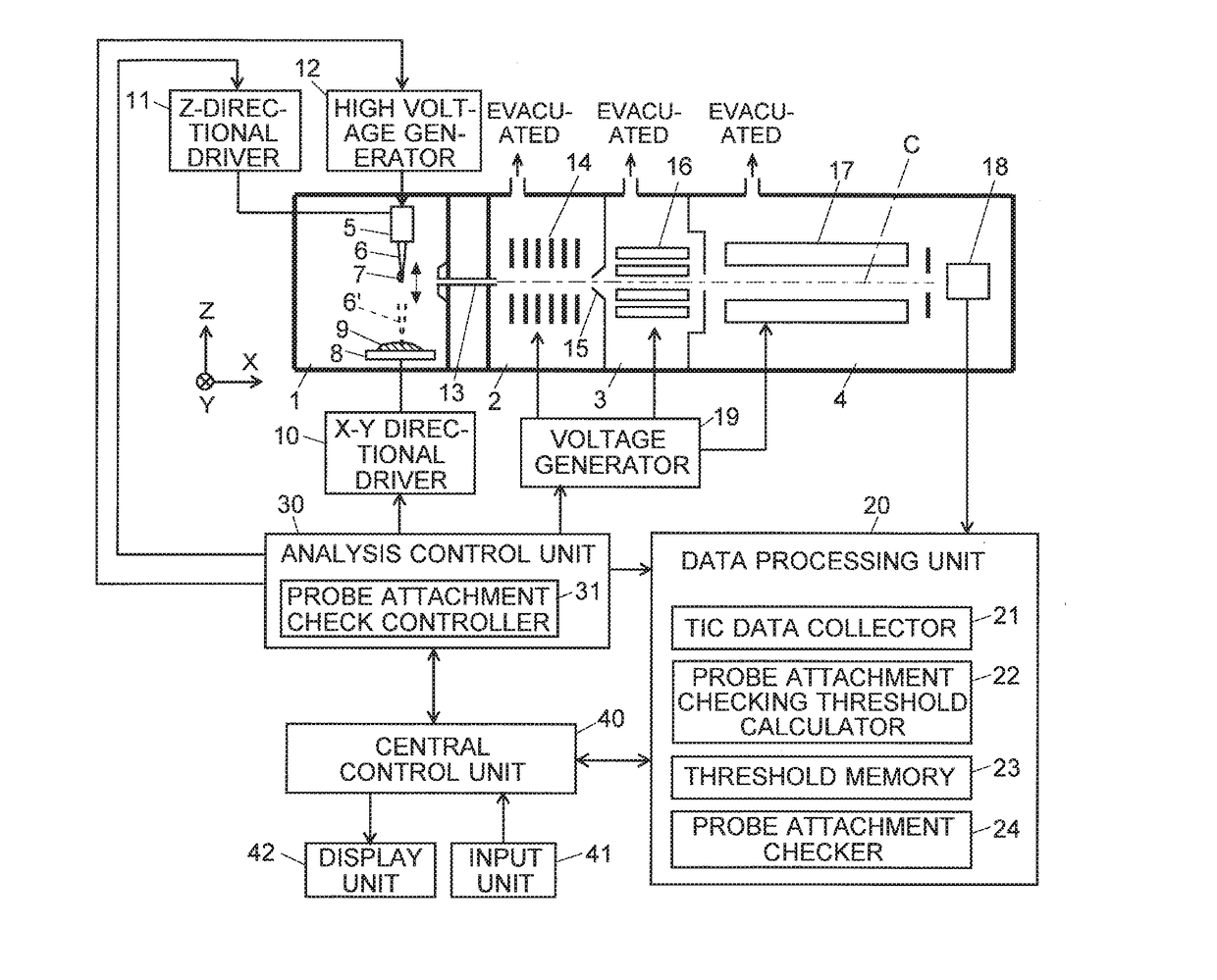
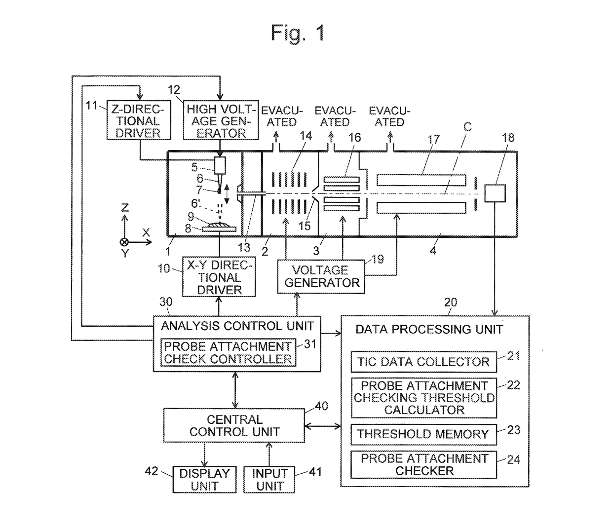
[0034]One embodiment of the mass spectrometer according to the present invention is described with reference to the attached drawings. FIG. 1 is a schematic configuration diagram of a mass spectrometer using a PESI ion source according to the present embodiment.

[0035]The mass spectrometer of the present embodiment has the configuration of a differential pumping system including an ionization chamber 1 for ionizing components in a sample under atmospheric pressure and an analysis chamber 4 for performing the mass separation and detection of ions under a high degree of vacuum, between which a plurality of (in the present example, two) intermediate vacuum chambers 2 and 3 are provided having their degrees of vacuum increased in a stepwise manner. Although not shown in FIG. 1, normally, the first intermediate vacuum chamber 2 is evacuated with a rotary pump, while the second intermediate vacuum chamber 3 and the analysis chamber 4 are evacuated with a turbo molecular pump in addition to...


PUM


Abstract

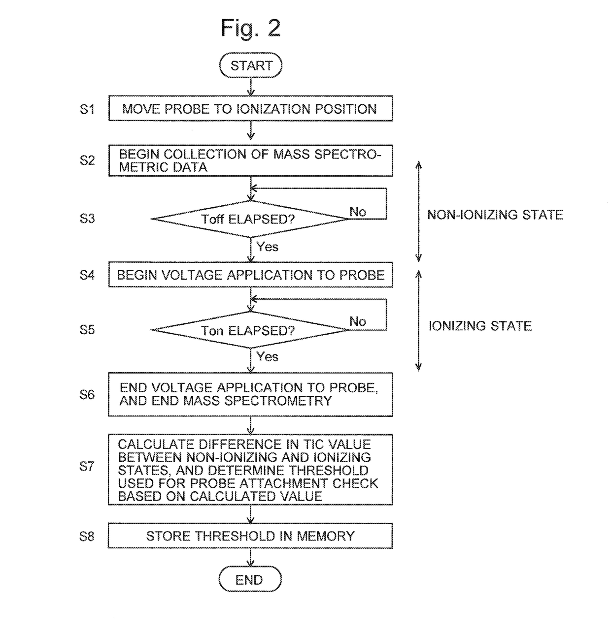
Before a sample is pierced with a probe of a PESI ion source, a total ion current is measured under a condition with no voltage applied from a high voltage generator to the probe as well as under a condition with the voltage applied. If the probe is properly attached to the holder, a considerable difference in total ion current occurs between the period with no voltage applied and the period with the voltage applied. By comparison, if the probe is improperly attached, no significant difference in the total ion current occurs between the period with no voltage applied and the period with the voltage applied. Referring to a threshold determined under the normal condition, a probe attachment checker detects an insufficient attachment of the probe by checking the difference in the total ion current, and displays an error message on a display unit if an improper attachment is detected.

Description

TECHNICAL FIELD[0001]The present invention relates to a mass spectrometer, and more specifically to a mass spectrometer having an ion source using a probe electrospray ionization method.BACKGROUND ART[0002]In recent years, for the diagnosis of cancers or similar purposes, mass spectrometers capable of a real-time measurement of specific substances (tumor markers) contained in biological tissues have been actively developed.[0003]Patent Literature 1 and Non Patent Literature 1 disclose a cancer diagnosis assistance system using a mass spectrometer having an ion source using a probe electrospray ionization (PESI) method, which is one type of atmospheric ionization method.[0004]The PESI method is a comparatively new ionization method. A PESI ion source includes an electrically conductive probe, a displacement section for driving at least either the probe or sample so as to make the sample adhere to the tip of the probe, and a high voltage generator for applying a high voltage to the pr...

Claims


Application Information

Patent Timeline
Patent Type & Authority Applications(United States)
IPC IPC(8): H01J49/16H01J49/02
CPCH01J49/025H01J49/165H01J49/0031H01J49/142
Inventor UEDA, HIROKOUCHIDA, TAKESHI
Owner SHIMADZU CORP
Learn More