
Method and system for monitoring state of charge (SOC) of flow battery system, flow battery based on redundancy design of soc detection device, method and device for determining actual capacity of flow battery, and method and system for estimating input-output characteristic of alternating-current side of flow battery

a flow battery and state of charge technology, applied in the field of flow batteries, can solve the problems of serious impact on operating safety and stability, management system cannot, and the real-time and accurate state of charge (soc) cannot be monitored and calculated comprehensively and completely, so as to prolong the service life of the battery, improve the service efficiency of the flow battery, and reduce the effect of soc measuremen

Active Publication Date: 2017-08-17
DALIAN RONGKE POWER
View PDF0 Cites 8 Cited by
  • Summary
  • Abstract
  • Description
  • Claims
  • Application Information

AI Technical Summary

Benefits of technology

The present invention provides a method and system for monitoring the state of charge (SOC) of a flow battery system, which has the following technical effects: 1. A detailed and accurate monitoring of the overall state of the flow battery system is possible through the integration of SOCs at multiple monitoring positions, ensuring real-time learning and improved service efficiency of the battery. 2. The reliability of SOC measurement is increased, faulty detection devices can be quickly identified and eliminated, and the actual capacity of the flow battery can be accurately determined. 3. The relationship between the SOC and various operating parameters is effectively sorted out, ensuring accurate determination of the battery's capacity and avoiding scheduling misalignment, over-charging / over-discharging, and misjudgment. 4. A method is provided for accurately estimating the input-output characteristic of the flow battery, taking into account the effects of auxiliary equipment, inversion equipment, and transformation equipment, providing more accurate guidance for user optimization.

Problems solved by technology

Such measurements are conducted according to unified standards, and real-time and accurate state of charge (SOC) cannot be monitored and calculated comprehensively and completely.
In addition, only one set of SOC detection devices is placed at a monitoring point in the prior art, which means that a battery management system cannot judge whether the detected SOC value is an accurate valve because of lack of reference data for comparison, when the SOC detection device is damaged, and it is possible to cause serious affects on the operating safety and stability of a flow battery body and a power station-level energy storage system in case of controlling and scheduling the flow battery based on inaccurate SOC value.
When the SOC detection device feeds back the inaccurate SOC value to the battery management system and a high-level energy management system, the inaccurate SOC value at least would affect subsequent operation and management of the flow battery, and in more serious cases will cause the situation that a scheduling instruction significantly fails to conform to the real state of the flow battery, thus causing forceful over-charging and over-discharging of the flow battery and seriously affecting the operating efficiency and stability of the whole energy storage system, and the phenomena, such as significant reduction of capacity and performance of the battery system, stack burnout and failure to continuous work of the battery system will occur if this case continues in this way.
When some operating parameters of the flow battery, such as temperature, operating mode, electrolyte flow and electrolyte temperature are off specifications, SOC obtained by the SOC detection device does not directly reflect the electric quantity actually dischargeable from the flow battery, and if SOC is simply used for reflecting chargeable and dischargeable capacities, it would cause inaccurate scheduling and over-charging / over-discharging of the flow battery, or misjudgment of the scheduling system and the like, thereby seriously affecting the operating efficiency and stability of the whole energy storage system and a power station.
Furthermore, the input-output characteristic of an alternating-current side of a flow battery is one of the problems that people concern, and is a premise that a user can use the flow battery favorably and accurately.
But, the flow battery itself has a magnetic drive pump, a heat exchange system, a ventilation system, a battery management system, a sensor and other auxiliary power consumptions, and for the flow battery, when it is charged or discharged, it is necessary to provide extra power consumption and energy to drive the auxiliary power consumptions to run, such that the input-output characteristic of the alternating-current side of the flow battery is significantly different from that of the traditional storage battery; secondly, self-discharging of the flow battery is also significantly different from that of the traditional battery, and is less affected by time, but greatly affected by a capacity-to-power ratio; finally, the same as the conventional storage battery, the flow battery also refers to the alternating-current / direct-current conversion efficiency of an energy storage inverter and a transformer.

Method used


Image

  • Method and system for monitoring state of charge (SOC) of flow battery system, flow battery based on redundancy design of soc detection device, method and device for determining actual capacity of flow battery, and method and system for estimating input-output characteristic of alternating-current side of flow battery
  • Method and system for monitoring state of charge (SOC) of flow battery system, flow battery based on redundancy design of soc detection device, method and device for determining actual capacity of flow battery, and method and system for estimating input-output characteristic of alternating-current side of flow battery
  • Method and system for monitoring state of charge (SOC) of flow battery system, flow battery based on redundancy design of soc detection device, method and device for determining actual capacity of flow battery, and method and system for estimating input-output characteristic of alternating-current side of flow battery

Examples


first embodiment

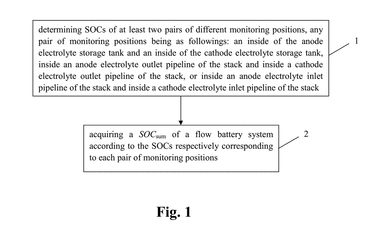
[0129]First, a method for monitoring state of charge (SOC) of a flow battery system according to the present invention will be explained in combination with drawings. FIG. 1 shows a method for monitoring state of charge (SOC) of a flow battery system. The flow battery system includes a stack, an anode electrolyte storage tank, a cathode electrolyte storage tank and an electrolyte circulating pipeline. The monitoring method includes the following steps:

[0130]Step 1: determining SOCs of at least two pairs of different monitoring positions. Each pair of the monitoring positions may be chosen from at inside of the anode electrolyte storage tank and inside of the cathode electrolyte storage tank, inside an anode electrolyte outlet pipeline of the stack and inside a cathode electrolyte outlet pipeline of the stack, or inside an anode electrolyte inlet pipeline of the stack and inside a cathode electrolyte inlet pipeline of the stack;

[0131]Step 2: according to the SOCs respectively corresp...

second embodiment

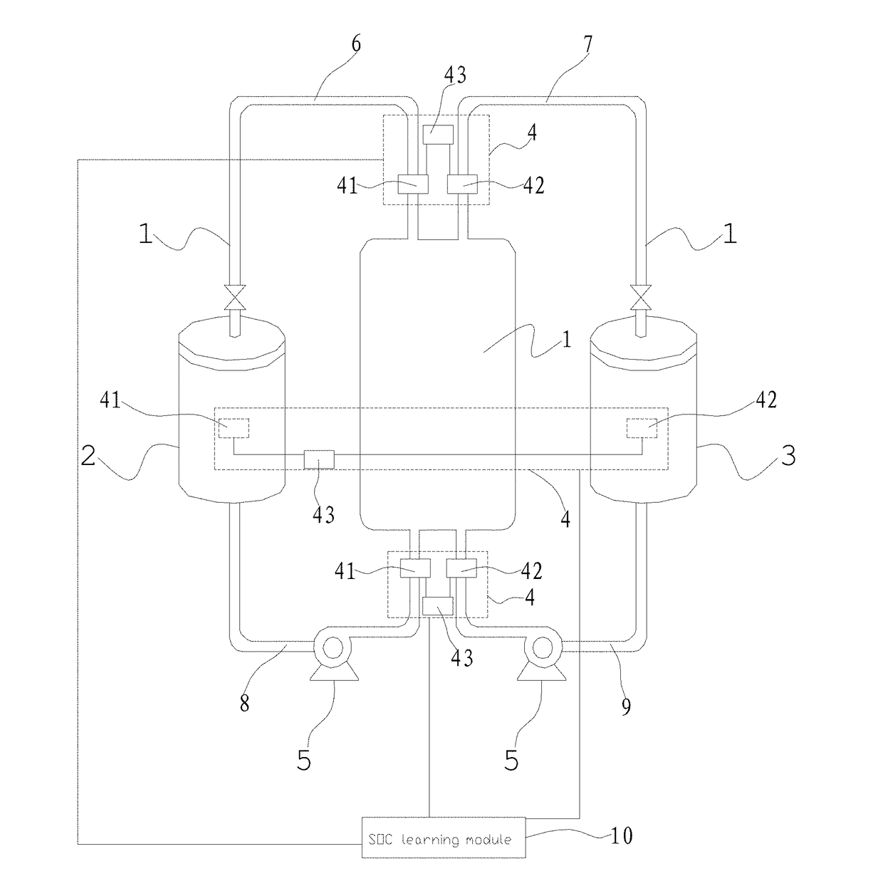
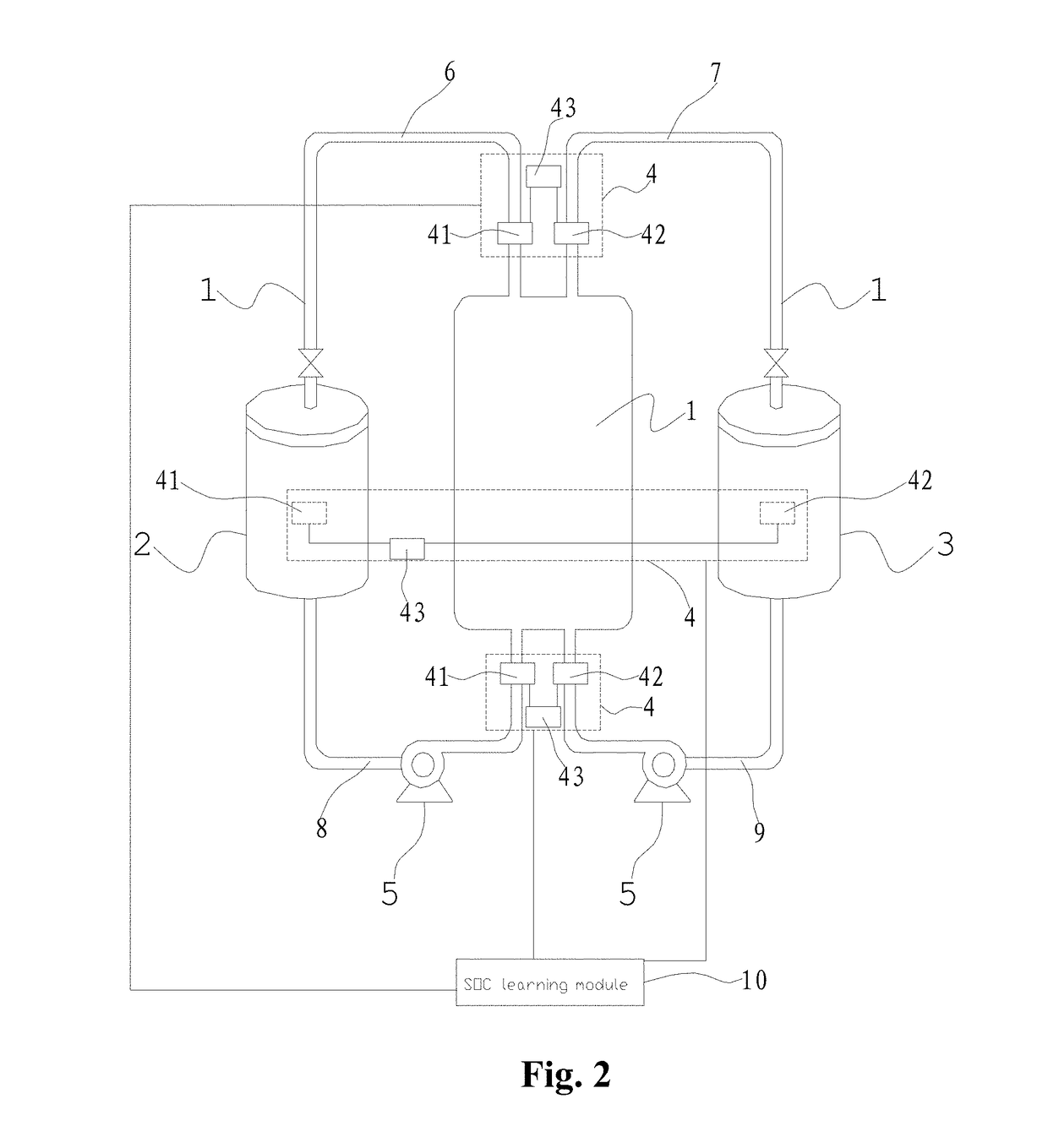
[0166]FIG. 2 is a structural schematic drawing representing a system for monitoring state of charge (SOC) of a flow battery system according to the present invention. As shown in FIG. 2, the flow battery system has a stack 1, an anode electrolyte storage tank 2, a cathode electrolyte storage tank 3 and an electrolyte circulating pipeline. The monitoring system includes a monitoring device configured to determine SOCs of at least two pairs of different monitoring positions. Each pair of monitoring positions is chosen from inside of the anode electrolyte storage tank 2 and inside of the cathode electrolyte storage tank 3, the anode electrolyte outlet pipeline of the stack 1 and the cathode electrolyte outlet pipeline of the stack 1, or the anode electrolyte inlet pipeline of the stack 1 and on the cathode electrolyte inlet pipeline of the stack 1. Preferably, the monitoring system further includes a connection monitoring device, and a SOC acquisition module 10 configured to acquire st...

third embodiment

[0172]FIG. 3 is a structural schematic drawing representing a flow battery based on a redundancy design of SOC detection devices according to the present invention. As shown in FIG. 3, the accuracy of measured SOC values is ensured by a redundancy design, i.e., at least two pairs of SOC detection devices 11 are provided at the same monitoring position. The monitoring positions may be any pair of positions chosen from inside of the anode electrolyte storage tank 2 and an inside of the cathode electrolyte storage tank 3, or on the electrolyte inlet pipeline of the stack and on the electrolyte outlet pipeline of the stack. I.E., an anode of each SOC detection device 11 can be arranged inside the anode electrolyte storage tank 2, and a cathode of the SOC detection device 11 can be arranged inside the cathode electrolyte storage tank 3; or, the anode of the SOC detection device 11 is connected with the anode electrolyte inlet pipeline of the stack, and the cathode of the SOC detection de...


PUM

PropertyMeasurementUnit
temperatureaaaaaaaaaa
current open-circuit voltageaaaaaaaaaa

Abstract

An apparatus monitors the state of charge (SOC) of a flow battery system. The monitoring method include determining SOCs of at least two pairs of different monitoring positions. A pair of monitoring position may be located inside of an anode electrolyte storage tank (2) and inside of a cathode electrolyte storage tank (3), or inside of an anode electrolyte outlet pipeline (6) of a stack and inside of a cathode electrolyte outlet pipeline (7) of the stack, or inside of an anode electrolyte inlet pipeline (8) of the stack and inside of a cathode electrolyte inlet pipeline (9) of the stack. The SOCsum of the flow battery system is acquired according to the SOCs corresponding to different pair of monitoring positions, respectively. The method ensures acquiring an SOC monitoring result timely and accurately.

Description

TECHNICAL FIELD[0001]The present invention belongs to the technical field of flow batteries, and more particularly relates to a method and system for monitoring state of charge (SOC) of a flow battery system, a flow battery based on a redundancy design of a SOC detection device, a method and device for determining an actual capacity of a flow battery, and a method and system for estimating an input-output characteristic of an alternating-current side of a flow battery.BACKGROUND ART[0002]A flow battery has become one of ideal choices of large-scale energy storage owing to its advantages, such as longevity, high safety, powerful over-charging and over-discharging capacities and environmental friendliness, and mainly functions in application markets including renewable energy source power stations, user side smart microgrids (in residential areas, industrial areas and communal facilities), etc. Correspondingly, the flow battery system has multiple functions, i.e., utilizing valley ele...

Claims


Application Information

Patent Timeline
Patent Type & Authority Applications(United States)
IPC IPC(8): H01M8/04537H01M8/20G01R31/36H01M8/18
CPCH01M8/04611H01M8/188H01M2250/10G01R31/3651H01M8/20Y02E60/50G01R31/367
Inventor ZHANG, YUZOU, YIZHANG, HUAMINLI, YINGWANG, XIAOLIHAN, XIHAN, LECONGZHANG, TAOMA, XIANGKUNZHAO, HONGGUI
Owner DALIAN RONGKE POWER
Learn More