
High linearity inductorless lna

a high-linearity, inductorless technology, applied in the direction of low-noise amplifiers, amplifiers with semiconductor devices/discharge tubes, amplifiers, etc., can solve the problems of deterioration of reception sensitivity, increase in nf (noise figure), line loss, etc., to improve a noise figure (nf), increase the trans-conductance of the lna, and make the ic (integrated circuit) more compa

Inactive Publication Date: 2017-08-24
DIALOG SEMICON KOREA INC
View PDF2 Cites 2 Cited by
  • Summary
  • Abstract
  • Description
  • Claims
  • Application Information

AI Technical Summary

Benefits of technology

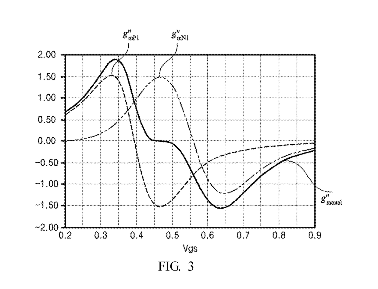
The present invention provides an inductor-less low noise amplifier (LNA) with a first amplifier and a second amplifier. This design makes the IC more compact and improves the noise figure by increasing the trans-conductance of the LNA by reusing a current of the first amplifier in the second amplifier. Additionally, the invention cancels the third-order trans-conductance of the first amplifier and the third-order trans-conductance of the second amplifier from each other to minimize a third-order intermodulation component and achieve high linearity. The first and second capacitors may protect the input terminals from ESD.

Problems solved by technology

This may produce a line loss, which may result in increase in NF (Noise Figure) and hence deterioration of reception sensitivity.
However, recent use of an LTE (Long Term Evolution) band ranging from 700 MHz to 2.4 GHz for mobile phones deteriorates the performance of the ISDB-T of the UHF frequency band (470 MHz to 707 MHz).
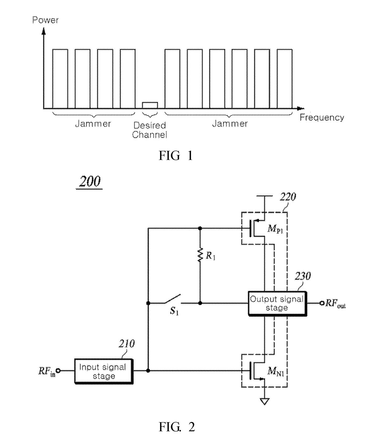
However, in mobile environments, if a large input signal with jammer power occurs in a frequency band adjacent to the desired channel, an interference may occurs between signals of the desired channel Therefore, there is need to reduce an interference between adjacent frequency bands.

Method used


Image

  • High linearity inductorless lna
  • High linearity inductorless lna
  • High linearity inductorless lna

Examples


Embodiment Construction

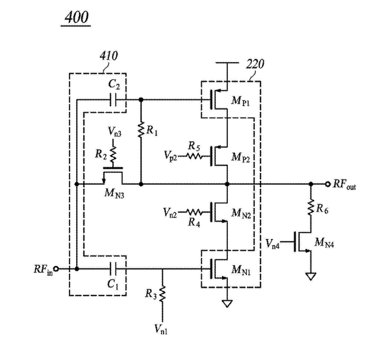
[0038]The above objects, features and advantages will become more clearly apparent from the following detailed description in conjunction with the accompanying drawings. Therefore, the technical ideas of the present invention can be easily understood and practiced by those skilled in the art. In the following detailed description of the present invention, concrete description on related functions or constructions will be omitted if it is deemed that the functions and / or constructions may unnecessarily obscure the gist of the present invention. Hereinafter, preferred embodiments of the present invention will be described in detail with reference to the accompanying drawings. Throughout the drawings, the same or similar elements are denoted by the same reference numerals.

[0039]FIG. 2 shows a simplified circuit of a low noise amplifier (LNA) according to an embodiment.

[0040]Referring to FIG. 2, an LNA 200 includes an input signal stage 210, an LNA core 220, a switch S1, a first resisto...


PUM


Abstract

An inductor-less low noise amplifier (LNA) with high linearity is disclosed. The low noise amplifier includes: an input signal stage receiving an input signal; a first amplifier configured to receive the input signal, generate a first amplification signal by amplifying the received input signal, and output the generated first amplification signal, as a first output signal, to a first output terminal; a second amplifier configured to receive the input signal, generate a second amplification signal by amplifying the received input signal, and output the generated second amplification signal, as a second output signal, to a second output terminal; an output signal stage outputting a superimposition signal obtained by superimposing the first output signal and the second output signal; a first resistor feeding back the superimposition signal to the input signal stage; and a switch connecting / disconnecting between the input signal stage and the output signal stage.

Description

BACKGROUND OF THE INVENTION[0001]Field of the Invention[0002]The present invention relates to an inductor-less LNA (Low Noise Amplifier) with a blocking function which is used in a communication system.[0003]Background of the Invention[0004]This section is just to provide background information related to embodiments of the present invention but is not intended to explain conventional techniques related thereto.[0005]As is known in the related art, ISDB-T (Integrated Service Digital Broadcasting Terrestrial) uses a UHF (Ultra High Frequency) frequency band (470 MHz to 707 MHz), ISDB-Tmm (Integrated Service Digital Broadcasting Terrestrial Mobile Multi-Media) uses a VHF (Very High Frequency) frequency band (170 MHz to 280 MHz), and ISDB-Tsb (Integrated Service Digital Broadcasting Terrestrial Sound Broadcasting) uses an LVHF (Low Very High Frequency) frequency band (90 MHz to 110 MHz). Among these, the ISDB-Tmm scheme has been devised for mobile broadcasting based on the ISDB-T schem...

Claims


Application Information

Patent Timeline
Patent Type & Authority Applications(United States)
IPC IPC(8): H03F1/30H03F3/193
CPCH03F1/303H03F3/193H03F2200/18H03F2200/451H03F2200/318H03F2200/294H03F1/301H03F1/302H03F1/307H03F1/308H03F1/3217H03F3/3011H03F3/3066H03F3/3076H03F2203/30084H03F2203/30117
Inventor KO, DONGHYUNHWANG, MYUNG WOON
Owner DIALOG SEMICON KOREA INC
Learn More