Thin film magnetic head, head gimbals assembly, head arm assembly, and magnetic disk unit
a magnetic head and gimbal technology, applied in the direction of magnetic recording, data recording, instruments, etc., can solve the problems of weakened signal magnetic field intensity, weakened signal recording performance of magnetic write element on magnetic disk, and impaired reliability of magnetic recording device, etc., to achieve stable floating of slider during operation, high dimension accuracy, and high density recording
- Summary
- Abstract
- Description
- Claims
- Application Information
AI Technical Summary
Benefits of technology
Problems solved by technology
Method used
Image
Examples
first modification
(First Modification)
[0064]For example, FIG. 5 is a sectional diagram illustrating a configuration of a main part of a thin film magnetic head 10A according to a first modification of the above-descried embodiment, and corresponds to FIG. 4 of the above-described embodiment (the thin film magnetic head 10). The thin film magnetic head 10A has a light shielding film 46 that is so formed as to cover at least the forward end surface 45S of the heatsink 45. Examples of a constituent material of the light shielding film 46 may include silicon carbide (SiC), silicon nitride (SiNx), and silicon dioxide (SiO2).
[0065]In the present modification, the light shielding film 46 shields the light that has traveled from the ABS 11S, thereby preventing the light from being incident on the forward end surface 45S of the heatsink 45. Thus, also in the present modification, generation of light returning from the forward end surface 45S of the heatsink 45 is suppressed. Effects similar to those in the ab...
second modification
(Second Modification)
[0066]FIG. 6 is a sectional diagram illustrating a configuration of a main part of a thin film magnetic head 10B according to a second modification of the above-described embodiment. In the thin film magnetic head 10 of the above-described embodiment, at least a part of the forward end surface 45S is inclined with respect to the ABS 11S in the XY plane. In contrast, in the present modification, at least a part of the forward end surface 45S is inclined with respect to the ABS 11S in the YZ cross-sectional plane. Even in this case, light reflected by the forward end surface 45S of the heatsink 45 travels toward a direction different from the direction of the entering light. Thus, Effects similar to those of the above-described embodiment can be expected.
third modification
(Third Modification)
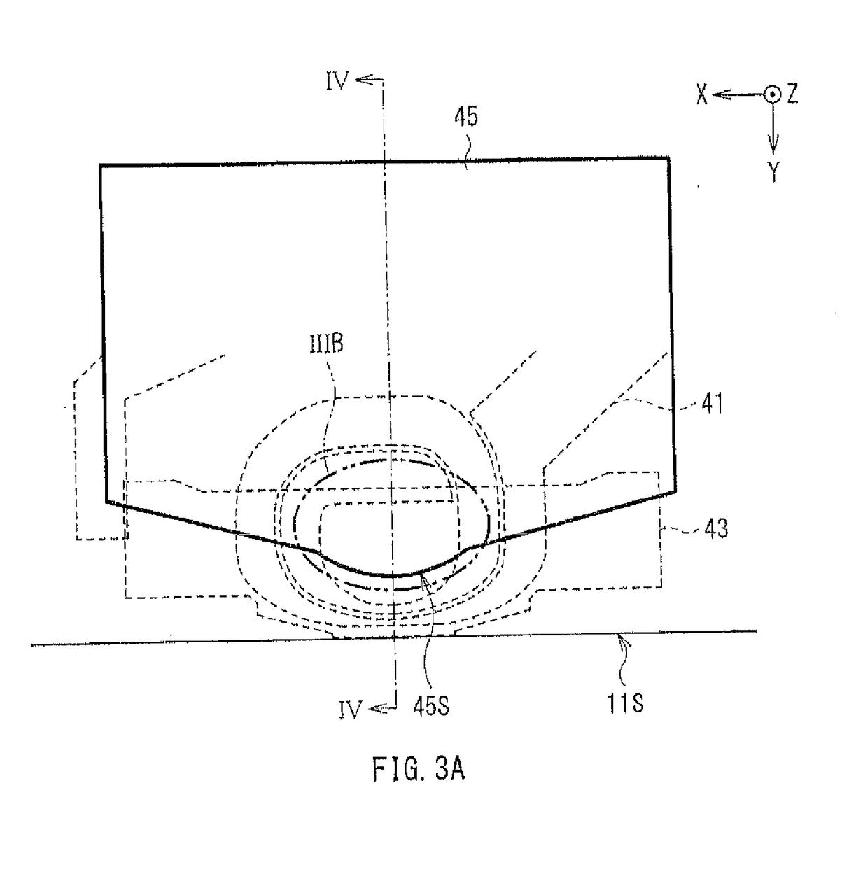
[0067]FIG. 7A and FIG. 7B are a sectional diagram and a plan view, respectively, each illustrating a configuration of a main part of a thin film magnetic head 10C according to a third modification of the above-described embodiment, and respectively correspond to FIG. 4 and FIG. 3 of the above-described embodiment (the thin film magnetic head 10). In the thin film magnetic head 10 of the above-described embodiment, the forward end surface 45S is a curved smooth surface. In contrast, in the present modification, the heatsink 45 includes a roughened forward end surface 45SS. The roughened forward end surface 45SS has an irregular structure that is formed by selective etching such as milling. In the present modification, although the incident light L1 reaches the heatsink 45, the light L1 is scattered by the roughened forward end surface 45SS, thereby being scattered light L2A. Thus, generation of light returning from the forward end surface 45SS of the heatsink 45 i...
PUM
| Property | Measurement | Unit |
|---|---|---|
| magnetic flux | aaaaa | aaaaa |
| reflection | aaaaa | aaaaa |
| surface roughness | aaaaa | aaaaa |
Abstract
Description
Claims
Application Information
 - R&D Engineer
- R&D Manager
- IP Professional
- Industry Leading Data Capabilities
- Powerful AI technology
- Patent DNA Extraction
Browse by: Latest US Patents, China's latest patents, Technical Efficacy Thesaurus, Application Domain, Technology Topic, Popular Technical Reports.
© 2024 PatSnap. All rights reserved.Legal|Privacy policy|Modern Slavery Act Transparency Statement|Sitemap|About US| Contact US: help@patsnap.com


