
Microfluidic Device for the Generation of Combinatorial Samples

a microfluidic device and combinatorial technology, applied in the field of microfluidic devices, can solve the problems of difficult to systematically generate all possible droplet pairs, poor control level, and strict limitations of the maximum flow rate and hence throughput of the negative pressure driven system, and achieve the effect of higher hydrodynamic resistan

Inactive Publication Date: 2017-10-05
EURO LAB FUER MOLEKULARBIOLOGIE EMBL
View PDF3 Cites 10 Cited by
  • Summary
  • Abstract
  • Description
  • Claims
  • Application Information

AI Technical Summary

Benefits of technology

The patent text is about a method for making droplets of a different phase fluid. The method takes into account the length, height, and width of the channel where the sample fluid flows through. This is to make sure that the sample fluid has a higher resistance to prevent it from entering the channel where the different phase fluid flows. This is important because it helps to control the formation of droplets. The text also mentions a way to increase the resistance of the channel using a fluidic resistor. Overall, the patent text provides technical details on how to make droplets with greater precision and control over their formation.

Problems solved by technology

While in theory this approach allows for the generation of many mixtures of different compounds (that can be screened for a desired effect or exploited for on-chip synthesis of compound libraries) the system has several limitations: The system is dependent on droplet fusion and only allows for the generation of combinatorial droplet pairs; The system is driven by negative pressure.
All flow is generated by aspirating from the outlet resulting in different droplet sizes for the different compounds when applying constant valve opening times. Even though this can be compensated in theory by adjusting the individual valve opening times, only a poor level of control can be achieved.
Since each infused compound needs a specific valve opening time, it seems very challenging to systematically generate all possible droplet pairs (and synchronize the generation of the individual droplets to allow for pairing).
Furthermore, a negative pressure driven system has strict limitations in terms of the maximum flow rates and hence the throughput.

Method used


Image

  • Microfluidic Device for the Generation of Combinatorial Samples
  • Microfluidic Device for the Generation of Combinatorial Samples
  • Microfluidic Device for the Generation of Combinatorial Samples

Examples


Embodiment Construction

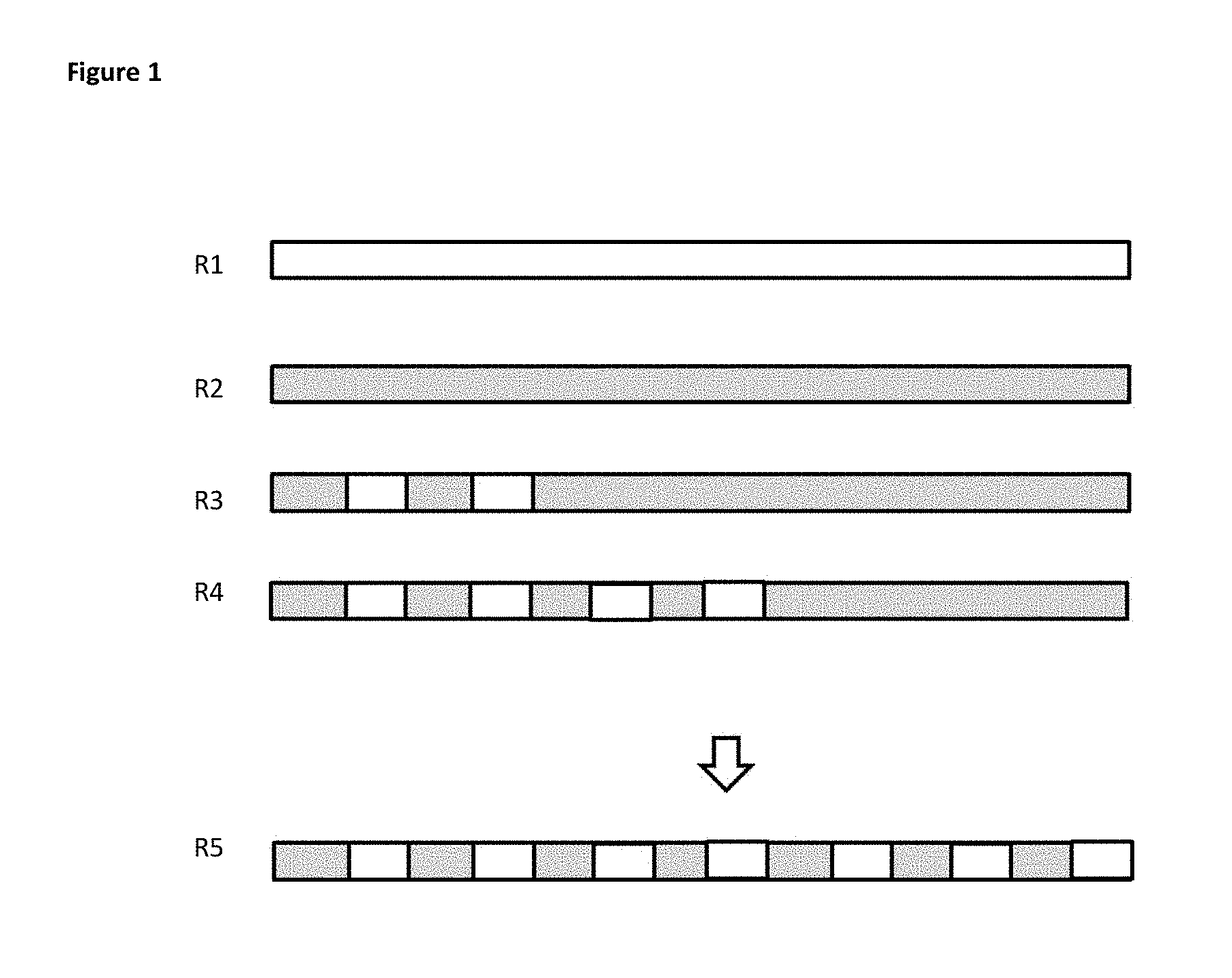
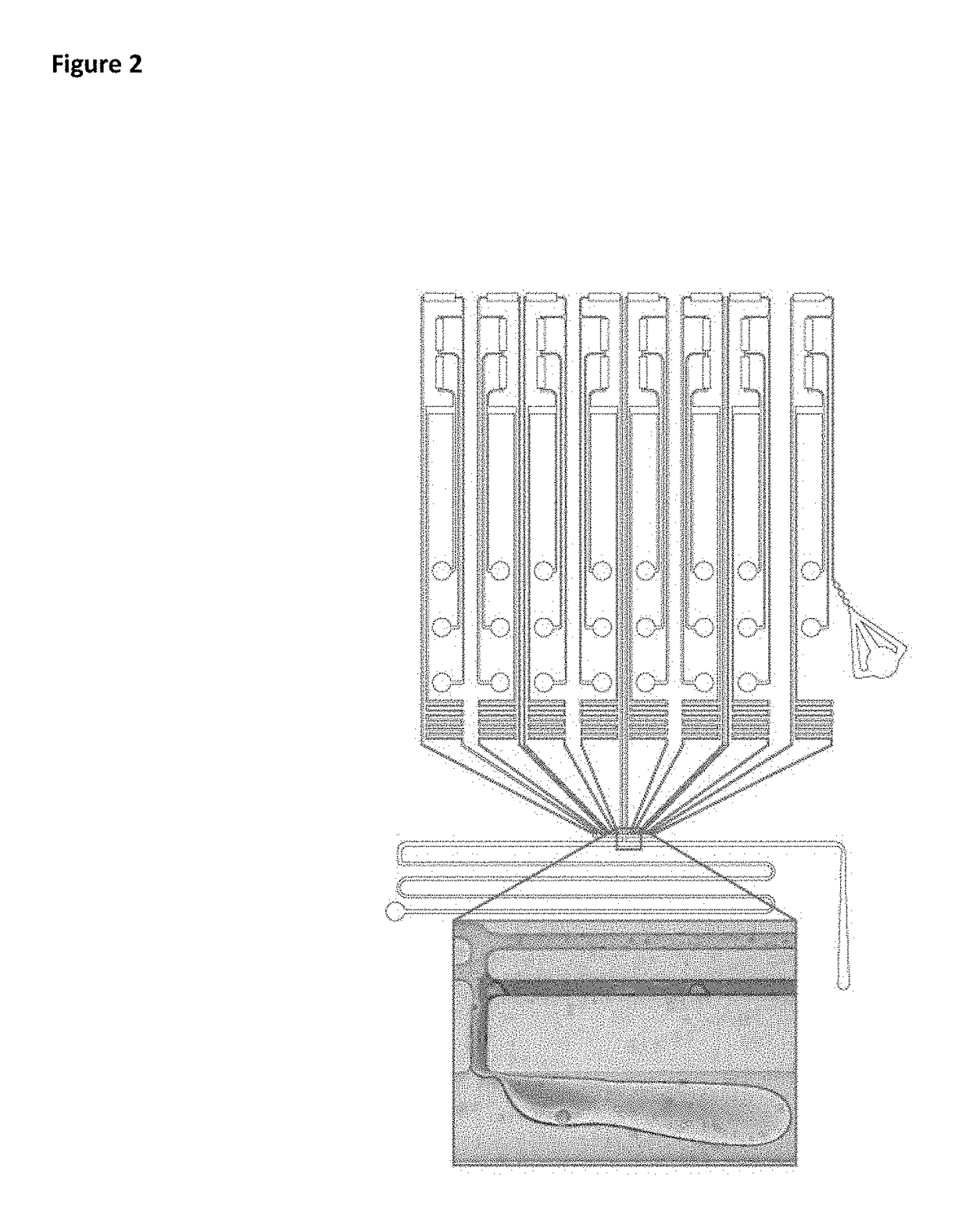
[0047]The present disclosure provides a microfluidic device allowing the generation and screening of combinatorial samples in a high throughput fashion. Starting with a number of n inlets (into which n different compounds can be injected) a total of up to 2n−1 chemically distinct samples can be generated in an automated fashion.

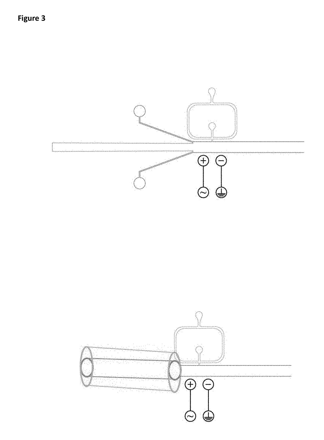
[0048]All channels providing a liquid to the droplet maker are arranged “upstream” of the droplet maker within the meaning of the instant disclosure. The outlet channel transporting the droplets or sequence of droplets is arranged “downstream” of the droplet maker. The terms droplets or plugs are used synonymously.

[0049]An aqueous liquid within the meaning of the present disclosure comprises every liquid that is miscible with water. In contrary, the immiscible phase comprises every liquid that is not miscible with water, like oil.

[0050]The device of the present disclosure can be used for generating an optical barcoding system for the newly generated combinato...


PUM

PropertyMeasurementUnit
timeaaaaaaaaaa
diameteraaaaaaaaaa
diameteraaaaaaaaaa

Abstract

The present disclosure relates to a microfluidic device and a method allowing the generating and screening of combinatorial samples. A microfluidic device for producing droplets of at least one sample into an immiscible phase is provided, the device comprising a droplet maker connecting an immiscible phase channel and a sample channel having at least one sample inlet connected to at least one sample inlet channel injecting the at least one sample into the sample channel, wherein the injection of the at least one sample is controlled by at least one sample valve, so that the at least one sample flows either towards a sample waste outlet or into the at least one sample inlet channel, wherein different sample inlet channel of the at least one sample inlet channel have the same hydrodynamic resistance resulting from the length, height and width of each sample inlet channel upstream of the droplet maker.

Description

FIELD OF THE INVENTION[0001]The present disclosure relates to a microfluidic device and a method allowing the generating and screening of combinatorial samples.BACKGROUND OF THE INVENTION[0002]Microfluidic devices consist typically of channel networks with channel dimensions of 10-500 μm in which liquids can be actuated by different means. More sophisticated microfluidic analysis systems have been developed using polymers with the purpose of miniaturizing existing lab scale experimental setups, to reduce sample reagent consumption and thereby cost, but also to gain sensitivity, throughput and multiplexing capabilities.[0003]One of the basic technologies for modern microfluidics was developed in the 1990s and has been termed soft lithography (Xia and Whitesides, 1998). It is based on earlier photolithographic techniques developed to fabricate microelectronic devices (Nall and Lathrop, 1958). Soft lithography allows fast prototyping of new microfluidic chip designs by replica folding....

Claims


Application Information

Patent Timeline
Patent Type & Authority Applications(United States)
IPC IPC(8): B01J19/00B01F5/04B01F3/08B01L3/00B01F13/00
CPCB01J19/0046B01F2215/0037B01L3/502738B01L3/502746B01L3/502715B01F13/0061B01F3/0807B01F5/0471B01L2200/0673B01L2300/0867B01J2219/00389B01J2219/00547B01J2219/00743B01J2219/00599B01L3/502784B01J2219/00418B01L2300/0883B01F23/41B01F25/314B01F33/30B01F33/301B01F2101/23
Inventor MERTEN, CHRISTOPHEICHER, DOMINICUTHARALA, RAMESH
Owner EURO LAB FUER MOLEKULARBIOLOGIE EMBL
Learn More