Variable filter circuit, RF front end circuit and communication device

Active Publication Date: 2017-10-05
MURATA MFG CO LTD
View PDF0 Cites 3 Cited by
  • Summary
  • Abstract
  • Description
  • Claims
  • Application Information

AI Technical Summary

Benefits of technology

[0018]According to the present disclosure, a band pass filter can be formed by combining a high pass filter that includes a capacitive element and a low pass filter that includes an inductive element. By controlling variable reactance units, steep attenuation characteristics can be obtained in bands close to the low-frequency side

Problems solved by technology

In the variable filter circuit of the related art, it is difficult to adjust the attenuation characteristic so as to be steep at frequencies close to the high-frequency side of the pass band and the low-frequency side of the pass band using the variable capacitors.
Consequently, in the case where the communication band of a certain communication signal to which the variable filter circuit is to be applied is adjacent to the communication band of another communication signal, even when the pass band of the variable filter circuit is made to match the desired communication band, it may not be possible to secure

Method used


Image

  • Variable filter circuit, RF front end circuit and communication device
  • Variable filter circuit, RF front end circuit and communication device
  • Variable filter circuit, RF front end circuit and communication device

Examples


first embodiment

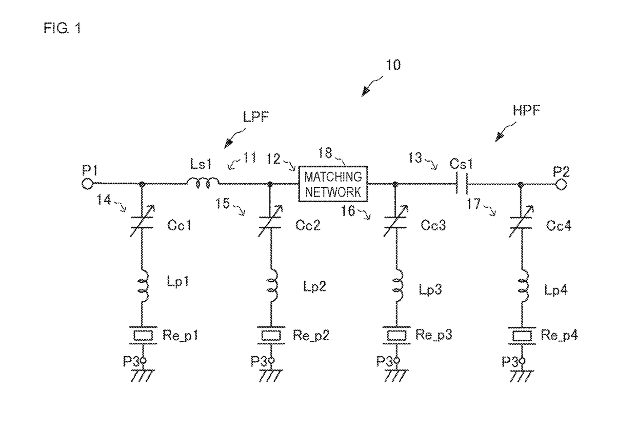
[0031]FIG. 1 is a circuit diagram that illustrates a variable filter circuit 10 according to a first embodiment of the present disclosure.

[0032]The variable filter circuit 10 includes ports P1, P2 and P3, series arms 11, 12 and 13, and parallel arms 14, 15, 16 and 17.

[0033]The port P1 is a first input / output terminal of the variable filter circuit 10. The port P2 is a second input / output terminal of the variable filter circuit 10. The ports P3 are ground connection terminals of the variable filter circuit 10.

[0034]One end of the series arm 11 is connected to the port P1 and the other end of the series arm 11 is connected to the series arm 12. One end of the series arm 12 is connected to the series arm 11 and the other end of the series arm 12 is connected to the series arm 13. One end of the series arm 13 is connected to the series arm 12 and the other end of the series arm 13 is connected to the port P2. In other words, the series arm 11, the series arm 12 and the series arm 13 are...

second embodiment

[0064]FIG. 5 is a circuit diagram that illustrates a variable filter circuit 10A according to a second embodiment of the present disclosure. In the following description, a case in which the variable filter circuit 10A is applied to a communication band divided into a plurality of narrow band channels will be described as an example.

[0065]The variable filter circuit 10A includes ports P1, P2 and P3, series arms 11, 12 and 13, and parallel arms 14A, 15A, 16A and 17A.

[0066]The parallel arm 14A includes a variable capacitor Cc1, an inductor Lp1, a switch SW1 and a plurality of resonators Re_p1. The switch SW1 has a function of selecting and connecting any one of the plurality of resonators Re_p1 to the parallel arm 14A. The parallel arm 15A includes a variable capacitor Cc2, an inductor Lp2, a switch SW2 and a plurality of resonators Re_p2. The switch SW2 has a function of selecting and connecting any one of the plurality of resonators Re_p2 to the parallel arm 15A. The resonance point...

third embodiment

[0079]FIG. 7 is a circuit diagram that illustrates a variable filter circuit 10B according to a third embodiment of the present disclosure.

[0080]The variable filter circuit 10B includes ports P1, P2 and P3, series arms 11, 12 and 13 and parallel arms 14B, 15B, 16B and 17B.

[0081]The parallel arm 14B includes a variable capacitor Cc1, a resonator Re_p1 and an inductor Lq1. One end of the inductor Lq1 is connected to a connection point between the variable capacitor Cc1 and the resonator Re_p1, and the other end of the inductor Lq1 is connected to a port P3. The parallel arm 15B includes a variable capacitor Cc2, a resonator Re_p2 and an inductor Lq2. One end of the inductor Lq2 is connected to a connection point between the variable capacitor Cc2 and the resonator Re_p2, and the other end of the inductor Lq2 is connected to a port P3. The parallel arm 16B includes a variable capacitor Cc3, a resonator Re_p3 and an inductor Lq3. One end of the inductor Lq3 is connected to a connection ...


PUM


Abstract

Provided is a variable filter circuit that can control the bandwidth and center frequency of a pass band, can realize steep attenuation characteristics in bands close to the pass band, and enables the total number of variable reactance units to be reduced. A variable filter circuit includes an inductor (Ls1) and a capacitor (Cs1), which are connected in series between a first input/output terminal (P1) and a second input/output terminal (P2), and resonators (Re_p1, Re_p2, Re_p3, Re_p4) and variable capacitors (Cc1, Cc2, Cc3, Cc4), which are connected in series between two ends of the inductor (Ls1) and the capacitor (Cs1) and ground connection terminals.

Description

[0001]This application is a continuation of International Application No. PCT / JP2015 / 079768 filed on Oct. 22, 2015 which claims priority from Japanese Patent Application No. 2014-229085 filed on Nov. 11, 2014. The contents of these applications are incorporated herein by reference in their entireties.BACKGROUNDTechnical Field[0002]The present disclosure relates to a variable filter circuit that has a variable bandpass characteristic, to an RF front end circuit that uses the variable filter circuit, and to a communication device that uses the RF front end circuit.[0003]In the related art, a band-pass-filter-type variable filter circuit has been proposed (for example, refer to Patent Document 1). The variable filter circuit of the related art has a ladder configuration in which a plurality of resonators is connected in parallel and series in an alternating manner. Two variable capacitors are connected in parallel and series with each resonator, and the frequency and the bandwidth of t...

Claims


Application Information

Patent Timeline
IPC IPC(8): H03H7/12H03H7/38
CPCH03H7/12H03H7/38H03F2200/451H03F3/195H03F2200/294H03F3/245H03F1/565H03F3/189H03F3/24H03H9/542H03H9/605H03H9/6483H03H2210/012H03H2210/015H03H2210/025
Inventor MORI, HIROTSUGU
Owner MURATA MFG CO LTD
Why Eureka
Try Eureka