Separators for enhanced flooded batteries, batteries, and related methods
Active Publication Date: 2017-10-12
DARAMIC LLC
View PDF4 Cites 13 Cited by
Summary
Abstract
Description
Claims
Application Information
AI Technical Summary
This helps you quickly interpret patents by identifying the three key elements:
Problems solved by technology
Method used
Benefits of technology
Benefits of technology
The patent is about an improved separator for batteries that can reduce resistance, increase power, and improve performance. The separator has decreased tortuosity, which means there are fewer turns for ions to take in the battery. The separator can also have increased pore size, more interconnected pores, and more open pores to improve the movement of ions. These improvements can lead to better performance and longer life of batteries. The invention also provides methods for making and using these improved separators, as well as some specific examples of their use in automobiles and other applications.
Problems solved by technology
Thus, a microporous separator with decreased tortuosity will present a shorter path for ions to travel through the separator, thereby decreasing electrical resistance.
Such decreased thickness may result in decreased overall weight of the battery separator, which in turn decreases the weight of the enhanced flooded battery in which the separator is used, which in turn decreases the weight of the overall vehicle in which the enhanced flooded battery is used.
Method used
Image
Click on the blue label to locate the original text in one second.
Reading with bidirectional positioning of images and text.
Examples
example 1
[0185]In Example 1, an enhanced flooded separator having a backweb thickness of 250 μm was made according to the present invention using UHMWPE, silica, and oil, and the silica used was a high oil absorption silica. An SEM of the inventive, low ER separator, was taken, see FIG. 15A.
[0186]Three shish-kebab regions, numbered Nos. 1, 2 and 3 respectively, were identified on the SEM of FIG. 15A, the SEM of the separator of Example 1. Then, FTIR spectra profiles were taken of each of the three shish-kebab regions, see FIGS. 15B-15D. The FTIR spectra taken of each of the three shish-kebab regions (Nos. 1, 2, and 3) of the SEM of FIG. 15A of the separator of Example 1 revealed the following peak position information and periodicity or repetition of the shish-kebab formations or morphology, shown in Table 9, below.
TABLE 9Shish-kebab region numberNo. 1No. 2No. 3Peak position0.11720.14840.1094Periodicity or0.0570.0470.085repetition of the(57 nm)(47 nm)(85 nm)shish-kebabformation
[0187]Ultimate...
example 2
[0188]Further, for Example 2, an enhanced flooded separator having a backweb thickness of 200 inn was made according to the present invention, in the same manner as Example 1 above, using UHMWPE, silica, and oil, and the silica used was a high oil absorption silica. An SEM of the inventive, low ER separator, was taken, see FIG. 16A.
[0189]Three shish-kebab regions, numbered Nos. 1, 2 and 3 respectively, were identified on the SEM of FIG. 16A, the SEM of the separator of Example 2. Then, FTIR spectra profiles were taken of each of the three shish-kebab regions, see FIGS. 16B-16D. The FTIR spectra taken of each of the three shish-kebab regions (Nos. 1, 2, and 3) of the SEM of FIG. 16A of the separator of Example 2 revealed the following peak position information and periodicity or repetition of the shish-kebab formations or morphology, shown in Table 10 below.
TABLE 10Shish-kebab region numberNo. 1No. 2No. 3Peak position0.11720.14060.07813Periodicity or0.0570.0470.085repetition of the(5...
example 3
[0191]For Example 3, an enhanced flooded separator having a backweb thickness of 250 μm was made according to the present invention, in the same manner as Example 1 above, using UHMWPE, silica, and oil, and the silica used was a high oil absorption silica. An SEM of the inventive, low ER separator, was taken, see FIG. 17A.
[0192]Three shish-kebab regions, numbered Nos. 1, 2 and 3 respectively, were identified on the SEM of FIG. 17A, the SEM of the separator of Example 3. Then, FTIR spectra profiles were taken of each of the three shish-kebab regions, see FIGS. 17B-17D. The FTIR spectra taken of each of the three shish-kebab regions (Nos. 1, 2, and 3) of the SEM of FIG. 17A of the separator of Example 3 revealed the following peak position information and periodicity or repetition of the shish-kebab formations or morphology, shown in Table 11 below.
TABLE 11Shish-kebab region numberNo. 1No. 2No. 3Peak position0.06250.054690.04688Periodicity or0.0630.0730.085repetition of the(63 nm)(73 ...
PUM
Abstract
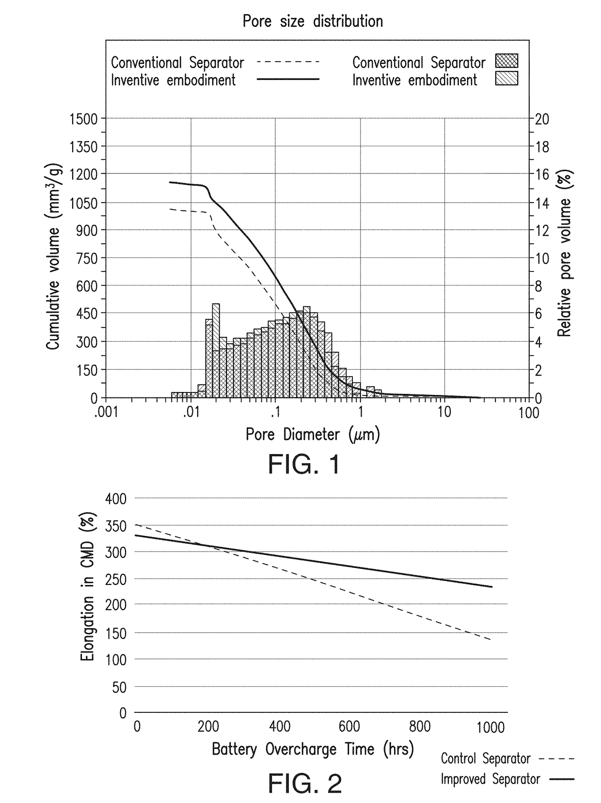
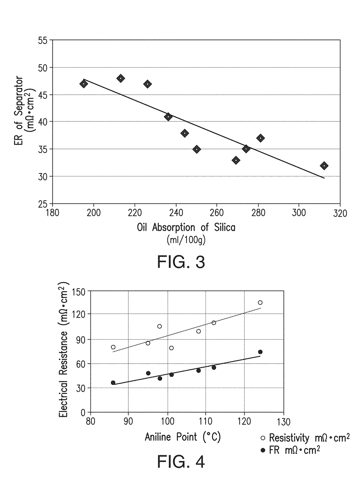
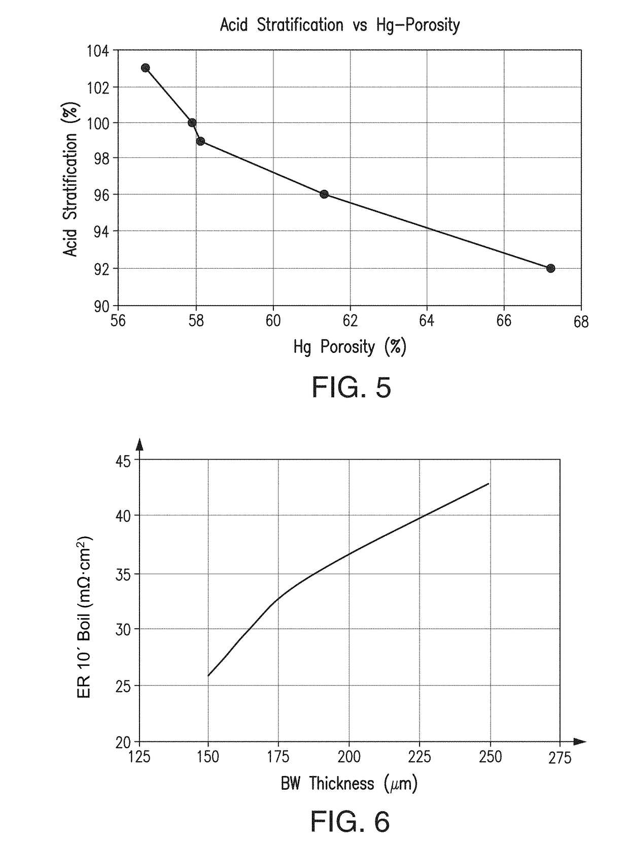
A battery separator has performance enhancing additives or coatings, fillers with increased friability, increased ionic diffusion, decreased tortuosity, increased wettability, reduced oil content, reduced thickness, decreased electrical resistance, and / or increased porosity. The separator in a battery reduces the water loss, lowers acid stratification, lowers the voltage drop, and / or increases the CCA. The separators include or exhibit performance enhancing additives or coatings, increased porosity, increased void volume, amorphous silica, higher oil absorption silica, higher silanol group silica, reduced electrical resistance, a shish-kebab structure or morphology, a polyolefin microporous membrane containing particle-like filler in an amount of 40% or more by weight of the membrane and ultrahigh molecular weightpolyethylene having shish-kebab formations and the average repetition periodicity of the kebab formation from 1 nm to 150 nm, decreased sheet thickness, decreased tortuosity, separators especially well-suited for enhanced flooded batteries.
Description
CROSS REFERENCE TO RELATED APPLICATIONS[0001]This application claims priority to and the benefit of U.S. Provisional Patent App. No. 62 / 319,959 filed 8 Apr. 2016.FIELD[0002]In accordance with at least selected embodiments, the present disclosure or invention is directed to novel or improved separators, battery separators, enhanced flooded battery separators, batteries, cells, and / or methods of manufacture and / or use of such separators, battery separators, enhanced flooded battery separators, cells, batteries, systems, methods, and / or vehicles using the same. In accordance with at least certain embodiments, the present disclosure or invention is directed to novel or improved battery separators, flooded lead acid battery separators, or enhanced flooded lead acid battery separators for starting lighting ignition (“SLI”) batteries, flooded batteries for deep cycle applications, and enhanced flooded batteries (“EFB”) and / or improved methods of making and / or using such improved separators...
Claims
Application Information
Patent Timeline
Application Date:The date an application was filed.
Publication Date:The date a patent or application was officially published.
First Publication Date:The earliest publication date of a patent with the same application number.
Issue Date:Publication date of the patent grant document.
PCT Entry Date:The Entry date of PCT National Phase.
Estimated Expiry Date:The statutory expiry date of a patent right according to the Patent Law, and it is the longest term of protection that the patent right can achieve without the termination of the patent right due to other reasons(Term extension factor has been taken into account ).
Invalid Date:Actual expiry date is based on effective date or publication date of legal transaction data of invalid patent.

