Method of joining aluminum and steel workpieces

a technology of steel workpieces and workpieces, which is applied in the direction of electrode vibration holders, manufacturing tools, and solvents, etc., can solve the problems of high consumable cost, more laborious installation of mechanical fasteners, and insurmountable technical and economical obstacles that accompany welding and/or mechanically fastening together an aluminum workpiece and a steel workpiece, so as to achieve the effect of increasing the electrical current applied to the consumable electrode rod

Inactive Publication Date: 2017-10-19
GM GLOBAL TECH OPERATIONS LLC
View PDF4 Cites 28 Cited by
  • Summary
  • Abstract
  • Description
  • Claims
  • Application Information

AI Technical Summary

Benefits of technology

[0012]The oscillating wire arc welding just discussed may be repeated one or more times to transfer multiple molten reaction material droplets to the faying surface of the steel workpiece. Those multiple molten reaction material droplets combine and solidify into the reaction material deposit. Moreover, as another variation, the electrical current applied to the consumable electrode rod may be increased when the molten reaction material droplet that has formed at the leading tip end of the electrode rod is in contact with the faying surface of the steel workpiece and the arc has been extinguished. In another variation, the step of compressing the reaction material deposit between the aluminum workpiece and the steel workpiece may be carried out by contacting a first side of the workpiece stack-up with a first electrode and contacting a second side of the workpiece stack-up with a second electrode, and converging the first and second welding electrodes to apply a clamping force against the first and second sides of the workpiece stack-up and to generate a compressive force on the reaction material deposit. In that regard, the step of heating the reaction material deposit may be carried out by passing an electrical current between the first and second welding electrodes and through the reaction material deposit. The electrical current that is passed between the first and second welding electrodes and through the reaction material deposit may be passed at a current level that ranges from 2 kA to 40 kA for a duration of 50 ms to 5000 ms.

Problems solved by technology

The joining of aluminum and steel workpieces through traditional welding practices, such as spot and laser welding, can be a challenging endeavor given the markedly different properties of aluminum and steel (e.g., solidus and liquidus temperatures and thermal and electrical conductivities).
Spot and laser welding processes are also complicated by the fact that a mechanically tough and electrically insulating refractory oxide layer is typically present at the surface of the aluminum workpiece.
But mechanical fasteners are more laborious to install and have high consumable costs compared to welding.
The technical and economical obstacles that accompany welding and / or mechanically fastening together an aluminum workpiece and a steel workpiece are not insurmountable.
Indeed, when the aluminum workpiece is heated to above its liquidus temperature and the resultant molten aluminum wets a broad surface of the steel workpiece, such as during the practice of resistance spot welding, a hard and brittle intermetallic layer comprised of Fe—Al intermetallic compounds forms along the unmelted faying surface of the steel workpiece.
This intermetallic layer is susceptible to rapid crack growth and, as a result, can be a cause of interfacial joint fracture when the joined aluminum and steel workpieces are subjected to loading.

Method used


Image

  • Method of joining aluminum and steel workpieces
  • Method of joining aluminum and steel workpieces
  • Method of joining aluminum and steel workpieces

Examples


Embodiment Construction

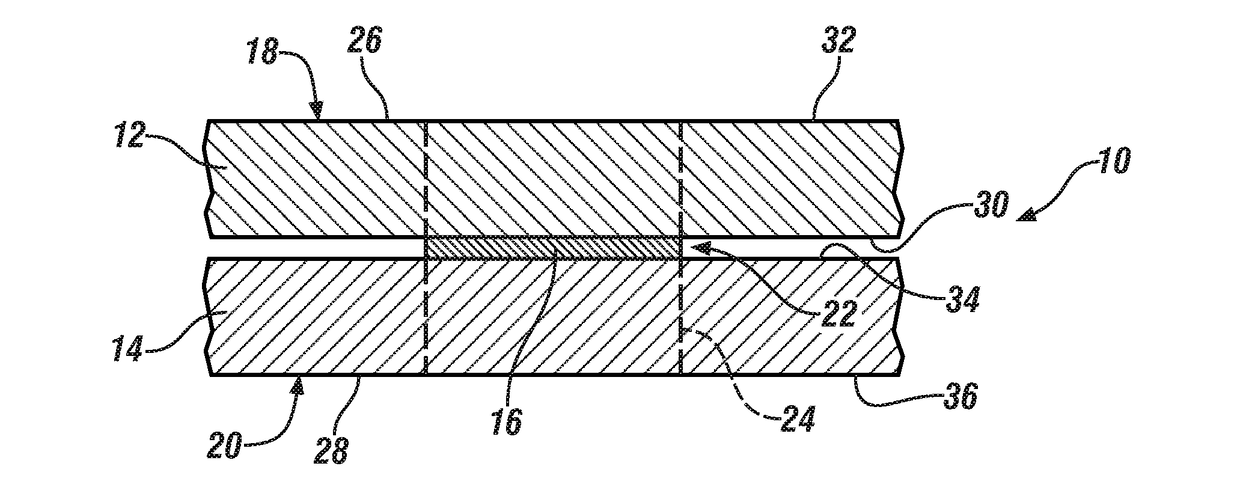
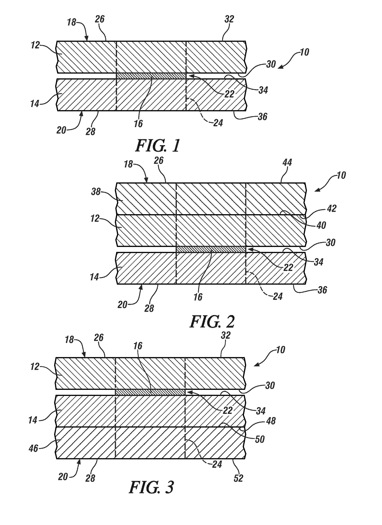
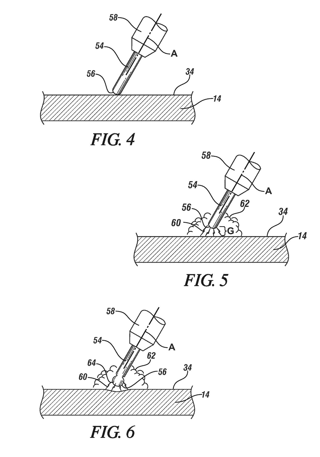
[0025]A method of joining an aluminum workpiece and a steel workpiece through reaction metallurgical joining is disclosed. Reaction metallurgical joining is a process in which a reaction material is heated and compressed between the opposed faying surfaces of the aluminum and steel workpieces to metallurgically join together the two workpiece surfaces. The reaction material is formulated to metallurgically react with the aluminum and the steel included in the aluminum and steel workpieces, respectively, when the reaction material is heated. A copper-based reaction material composition such as, for instance, pure unalloyed copper or a suitable copper alloy, can metallurgically react with both the aluminum and steel workpieces by having the capacity to wet steel on one hand and form a low-melting point eutectic alloy with aluminum on the other hand. Such a reaction material composition can thus form a bonding interface with both steel and aluminum when heated and then subsequently coo...


PUM

PropertyMeasurementUnit
currentaaaaaaaaaa
thicknessaaaaaaaaaa
thicknessaaaaaaaaaa

Abstract

A method of joining an aluminum workpiece and an adjacent overlapping steel workpiece by reaction metallurgical joining, and the resultant metallurgical joint formed between the two workpieces, are disclosed. The method involves compressing a reaction material located between the aluminum and steel workpieces and heating the reaction material momentarily to form a metallurgical joint that comprises bonding interface between the reaction material and the steel workpiece and a bonding interface between the reaction material and the aluminum workpiece. The reaction material is formulated to be able to interact with both aluminum and steel in order to establish the bonding interfaces of the metallurgical joint. Moreover, the practice of oscillating wire arc welding may be employed to deposit the reaction material in the form of a reaction material deposit onto the steel workpiece prior to assembling the steel and aluminum workpieces in a workpiece stack-up.

Description

CROSS-REFERENCE(S) TO RELATED APPLICATIONS[0001]This application claims the benefit of U.S. Provisional Application No. 62 / 324,658 filed on Apr. 19, 2016. The entire contents of the aforementioned provisional application are incorporated herein by reference.TECHNICAL FIELD[0002]The technical field of this disclosure relates generally to a method for joining an aluminum workpiece and a steel workpiece by way of reaction metallurgical joining.INTRODUCTION[0003]A number of manufacturing industries employ operations in which two or more metal workpieces are joined together. The automotive industry, for example, often uses various forms of welding and / or mechanical fastening to join together metal workpieces during the manufacture of vehicle structural members (e.g., body sides and cross members) and vehicle closure members (e.g., doors, hoods, trunk lids, and lift gates), among others. And while welding and fastening procedures have traditionally been practiced to join together certain ...

Claims


Application Information

Patent Timeline
Patent Type & Authority Applications(United States)
IPC IPC(8): B23K11/20B23K35/30B23K9/30C22C9/00B23K9/235
CPCB23K11/20B23K9/30C22C9/00B23K35/302B23K9/235B23K1/0008B23K1/19B23K9/042B23K9/232B23K11/115B23K11/163B23K2101/006B23K2101/18B23K2101/34B23K2103/20
Inventor PERRY, THOMAS A.SCHROTH, JAMES G.SIGLER, DAVID R.
Owner GM GLOBAL TECH OPERATIONS LLC
Why Eureka
Try Eureka