Photonic beamforming system for a phased array antenna receiver

a beamforming system and phased array technology, applied in the direction of rf signal generation/processing, fiber transmission, optical transmission, etc., can solve the problem of serious limitation of spectrally rich signals, phase shift applied to a given signal only correct for a single frequency, and difficulty in implementing tunable electrical delay lines, so as to reduce the linewidth requirements of the input laser source.

a beamforming system and phased array technology, applied in the direction of rf signal generation/processing, fiber transmission, optical transmission, etc., can solve the problem of serious limitation of spectrally rich signals, phase shift applied to a given signal only correct for a single frequency, and difficulty in implementing tunable electrical delay lines, so as to reduce the linewidth requirements of the input laser source.

US20170310006A1Active Publication Date: 2017-10-26INST DE TELECOMUNICACOES

Image

  • Photonic beamforming system for a phased array antenna receiver
  • Photonic beamforming system for a phased array antenna receiver
  • Photonic beamforming system for a phased array antenna receiver

Examples


embodiments

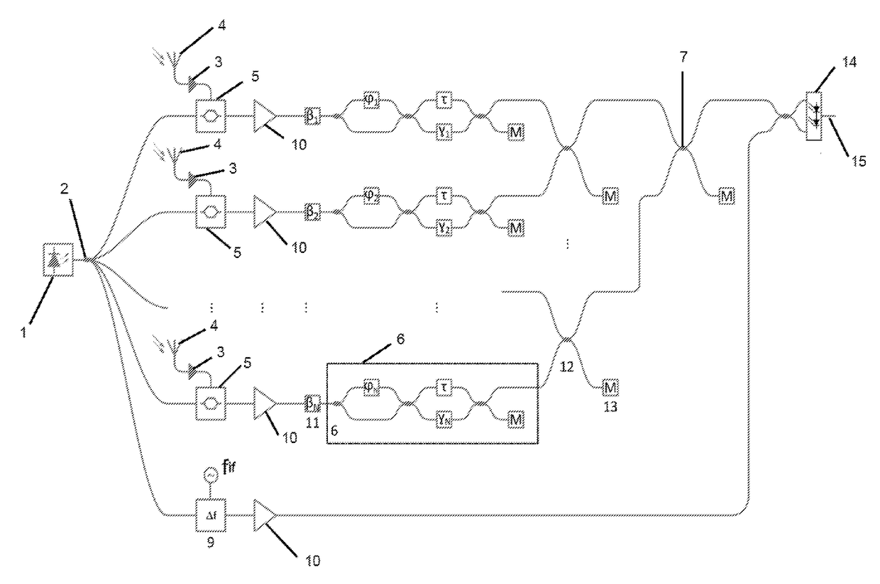
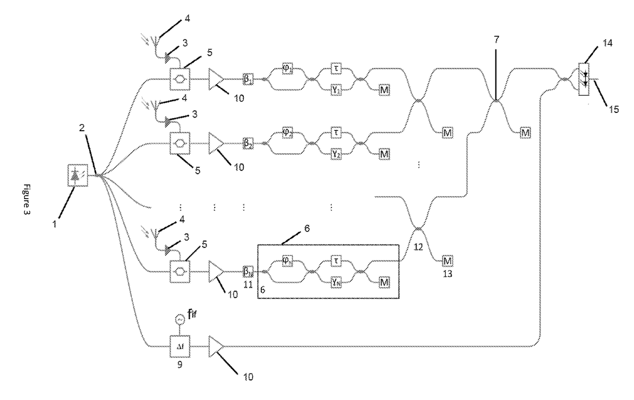
[0100]A second embodiment is shown in FIG. 3. This embodiment incorporates all the advantageous features described in the previous section. Besides the N upper paths required to process the input signals from all the N antenna elements, there is another path at the bottom used to generate the frequency-shifted OLO signal. A copy of the input laser signal is frequency-shifted by a frequency shifter (9) from a frequency of ƒOC to a frequency of ƒOLO=ƒOC+ƒIF.

[0101]After electro-optic modulation, for the input RF signals, and frequency-shifting, for the OLO, the resulting signals are amplified by an array of optical amplifiers (10). Each modulated optical signal is then phase-shifted by a phase shifter βi (11), i=1, . . . , N. The array of phase shifters (11) is useful not only for individual RF photonic phase shifting, but also for active phase stabilization of each path. The use of phase shifters (11) can be avoided if electro-optic phase modulation is used, as phase shifting can be p...


PUM


Abstract

It is an object of the present invention a photonic system to perform beamforming of a radio signal received by a phased array antenna with N antenna elements. It provides true-time delay beamforming enabled by tunable optical delay lines (6) with a periodic frequency response.The present invention provides four key advantages: photonic RF phase shifting; highly-sensitive coherent detection with intrinsic photonic frequency downconversion; phase noise cancellation, since a frequency-shifted optical local oscillator can be derived from a same laser source (1) used to feed electro-optic modulators (5); and the possibility of only requiring a single delay line, shared amongst all tunable optical delay lines. Such set of advantages makes the proposed system extremely attractive for high-end wireless receivers, required for demanding applications such as satellite communication systems and broadband wireless signal transmission.

Description

FIELD OF THE INVENTION[0001]It is an object of the present invention a photonic system to perform beamforming of the radio signal received by a phased array antenna with N antenna elements.[0002]The photonic system of the present invention performs beamforming of the radio signal received by a phased array antenna, The system provides true-time delay beamforming enabled by tunable optical delay lines with a periodic frequency response. In one of the possible embodiments, a Mach-Zehnder delay interferometer is able provide such operation.[0003]Such interferometer has a preset differential time delay between its arms / branches, and also an adjustable coupling ratio between the powers applied to its arms. The time delay can be configured by adjusting such coupling ratio. In the first stage of the proposed system the RF signals output by all antenna elements of the phased array antenna are converted to the optical domain using an array of electro-optic modulators. The amplitude of the mo...

Claims


Application Information

Patent Timeline
26 Oct 2017
Publication
US20170310006A1
IPC
H01Q3/26; H01Q3/22; H04B10/2575; H04B10/64
CPC
H01Q3/2676; H04B10/64; H04B2210/006; H01Q3/22; H04B10/2575; H04B7/086; H04B10/615; H04B10/616
Inventors
VIDAL DRUMMOND, MIGUEL; NUNES NOGUEIRA, ROGERIO