Compact height torque sensing articulation axis assembly

a torque sensing and articulation axis technology, applied in the field of compact height torque sensing articulation axis assembly, can solve the problems of increasing the tension of the pull wire rather than a change in the articulation of the catheter, unanticipated or unmodeled constraints imposed by the patient, and expected catheter tip articulation, so as to achieve the effect of minimizing the height of the articulation drive assembly

Active Publication Date: 2017-11-02
AURIS HEALTH INC
View PDF0 Cites 49 Cited by
  • Summary
  • Abstract
  • Description
  • Claims
  • Application Information

AI Technical Summary

Benefits of technology

[0016]In some embodiments, a robotic surgical system may include a control system electrically connectable to an input device and configured to receive information for positioning or orienting a catheter from the input device; the system may further include an instrument driver operatively connected to the control system. The instrument driver may include one or more articulation drive assemblies. Each articulation drive assembly may include: a motor configured to provide rotary output to actuate movement of an elongate member or other component of the surgical system; a gearbox configured to modify the rotary output of the motor; and a reactive torque sensor coaxial with and radially surrounding at least a portion of the rotary output motor and / or the gearbox. The motor may be at least partially within the reactive torque sensor to minimize height of the articulation drive assembly. The control system may be configured to actuate the motor in response to the information, from the input device, to drive an output shaft in communication with the elongate member. The instrument driver may be configured to determine an output shaft torque imparted by the output shaft to the elongate member. The reactive torque sensor may be coaxial with, and at least partially radially surround, both the rotary output motor and the gearbox. At least one of the gearbox and the motor may be mounted to the reactive torque sensor by a first mounting flange. The articulation drive assembly may be mounted to the instrument driver housing by the second mounting flange of the torque sensor. The first and second flanges may be configured to ground torque loads. The reactive torque sensor may further include at least one load cell configured to measure the output shaft torque. The articulation drive assembly may be configured to adjust a pullwire tension to impart motion to a tip of a catheter or elongate device or alternatively may be configured to rotate a drive wheel or roller on an active drive device to insert, retract, or rotate an elongate device. The system may further include a motor cable wrapped at least once around and communicatively coupled to at least one of the motor, the gearbox, and the torque sensor. The cable may be clock spring wound.

Problems solved by technology

However, at times, pullwire displacement may not result in the expected catheter tip articulation.
Various elements can affect the amount of articulation for a given pullwire actuation, including the presence of unanticipated or un-modeled constraints imposed by the patient's anatomy, particularly given the tortuous path that the catheter must traverse.
Additionally, pullwire displacement may result in an increase in pullwire tension rather than a change in catheter articulation if there is undetected slack in the pullwire.
When unanticipated and un-modeled conditions or constraints exist, kinematic modeling may not accurately predict catheter tip movement leading to errors.
While the rotational position of the output shaft may be determined from the encoder, the torque applied at the output shaft may not be able to be precisely calculated because of variations in transmission efficiency and the effects of perturbations on the system due to catheter construction shape and use.
Moreover, the encoder may not provide accurate information on load.
However, if higher insertion forces are encountered, the catheters or guidewires may slip between the rollers and not be inserted as far as intended.
There are size constraints on all dimensions of the instrument driver.
If the instrument driver of a surgical system is too wide, then it will obscure certain parts of the anatomy for an external imaging source such as a fluoroscopy system.
If the instrument driver is too long, then the carriages cannot come close enough together on telescoping robotic systems, and the inner catheter cannot be inserted as far into the outer catheter, resulting in a need for longer catheters and a lack of control.
If the instrument driver is too tall, then the angle of entry into the patient becomes too steep, resulting in access site injuries such as bleeding or hematomas.
Because the sheath carriage and leader carriage are traditionally aligned along the insertion axis, this configuration results in the RCM taking up significant space over the patient.
If the RCM is too large, the system can interfere with other system operations (such as operation of the C-arm and / or monitors).
If the RCM is too large, the RCM may obstruct the imaging device's ability to capture the entire desired imaging field.
Accordingly, despite the benefits of torque sensing, many robotic catheter systems do not have torque sensing due to the size constraints mentioned here.
However, differences between predicted and actual catheter position can result from the reliance by the kinematic model on certain assumptions and the lack of certain information.
Even with rigid structures, external forces, even gravity, may disrupt the ability to solve the location equation given the information above.
However, when a load is placed on the beam, the distal end will deflect, or strain under the load.
Even in a purely elastic response to the load, the location or orientation of the distal end of the beam is impossible to predict without knowing the magnitude, the direction, and the location of the external load.

Method used


Image

  • Compact height torque sensing articulation axis assembly
  • Compact height torque sensing articulation axis assembly
  • Compact height torque sensing articulation axis assembly

Examples


Embodiment Construction

[0037]Referring now to the discussion that follows and also to the drawings, illustrative approaches to the disclosed assemblies are shown in detail. Although the drawings represent some possible approaches, the drawings are not necessarily to scale and certain features may be exaggerated, removed, or partially sectioned to better illustrate and explain the present disclosure. Further, the descriptions set forth herein are not intended to be exhaustive or otherwise limit or restrict the claims to the precise forms and configurations shown in the drawings and disclosed in the following detailed description.

[0038]As used herein, the term “catheter” may refer to any flexible elongate medical instrument.

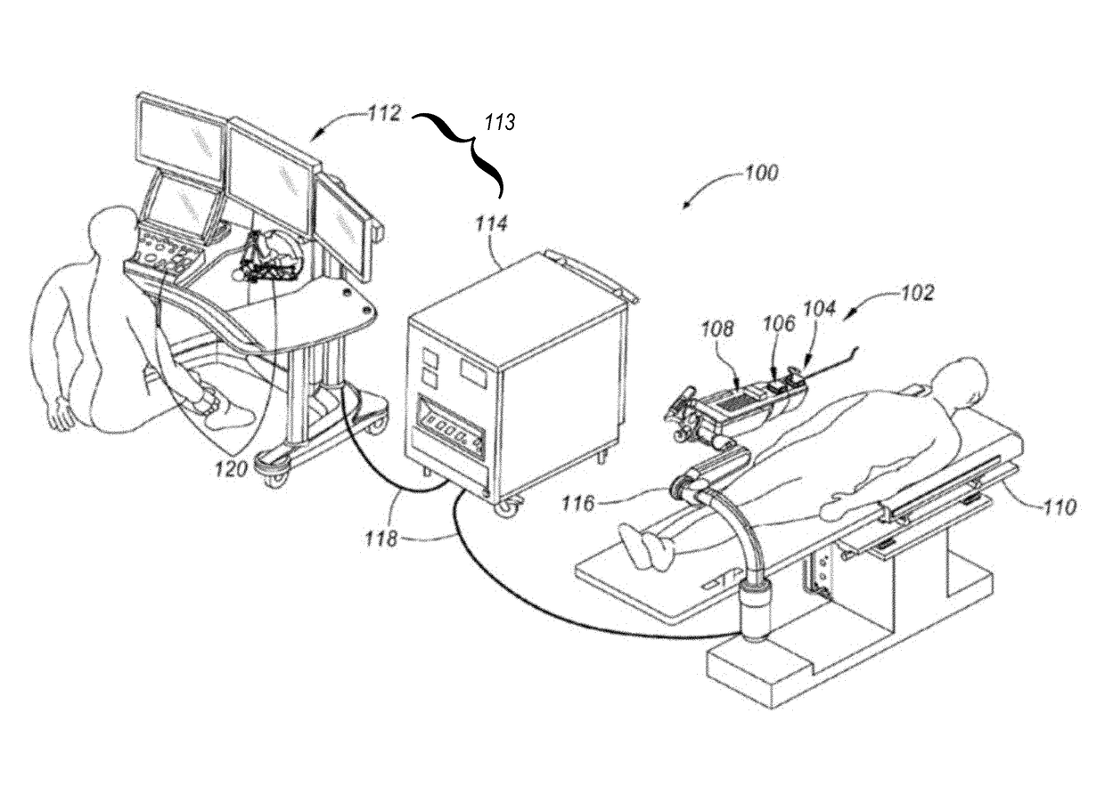
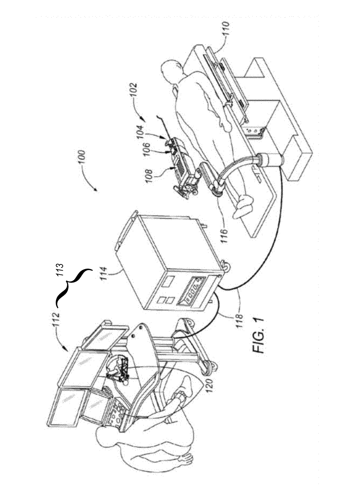
[0039]Referring to FIG. 1, a robotic surgical system 100 is illustrated in which an apparatus, a system, and / or method may be implemented according to various exemplary illustrations. The system 100 may include a robotic catheter assembly 102 having one or more elongate members such as a...


PUM


Abstract

A compact height torque sensing articulation axis assembly is disclosed herein having a torque sensor, an assembly mounting flange, a motor, a motor gearbox, a gearbox output shaft, an encoder, and a cable. The assembly may sense tension on robotic catheter pullwires in an articulating catheter and/or torque on a robotic output axis using the torque sensor. Disclosed embodiments may advantageously be used to achieve small, lightweight robotic catheter systems.

Description

CROSS-REFERENCE TO RELATED APPLICATIONS[0001]This application claims priority to U.S. Provisional Application 62 / 329,617, filed Apr. 29, 2016, the entirety of which is hereby incorporated by reference herein for any and all purposes as if set forth herein in its entirety. Embodiments described in this application may be used in combination or conjunction with the subject matter described in one or more of the following, each of which is hereby fully incorporated by reference for any and all purposes as if set forth herein in their entireties:[0002]U.S. patent application Ser. No. 13 / 835,136, filed Mar. 15, 2013, entitled “ACTIVE DRIVE MECHANISM FOR SIMULTANEOUS ROTATION AND TRANSLATION;”[0003]U.S. patent application Ser. No. 13 / 839,967, filed Mar. 15, 2013, entitled “VASCULAR REMOTE CATHETER MANIPULATOR;”[0004]U.S. patent application Ser. No. 14 / 214,711, filed Mar. 14, 2013, entitled “CATHETER TENSION SENSING;” and[0005]U.S. Pat. No. 9,173,713, issued Nov. 3, 2015, entitled “TORQUE-...

Claims


Application Information

Patent Timeline
Patent Type & Authority Applications(United States)
IPC IPC(8): A61M25/01H02K7/116A61B90/00H02K11/21H02P6/14H02K11/24F16H57/02
CPCA61M25/0113A61M25/0147A61B90/06H02K7/116F16H57/02H02K11/24H02P6/14A61B2090/066F16H2057/02034H02K11/21A61B2017/00323A61B34/30A61B2034/301A61B2090/064F16H57/08F16H57/082F16H2057/016F16H2057/02039
Inventor COVINGTON, TRAVISWILSON, COLIN
Owner AURIS HEALTH INC
Why Eureka
Try Eureka