Self contained internal chamber for a projectile

a projectile and self-contained technology, applied in the field of ammunition, can solve the problems of increasing the friction of the barrel/barrel, the pressure peak is substantially higher than the average pressure experienced, and the surface deformation of the barrel, so as to achieve the effect of reducing the pressure peak, reducing the pressure, and increasing the flexibility of pressure manipulation

Active Publication Date: 2017-11-09
DIMOSTHENIS PANOUSAKIS
View PDF8 Cites 10 Cited by
  • Summary
  • Abstract
  • Description
  • Claims
  • Application Information

AI Technical Summary

Benefits of technology

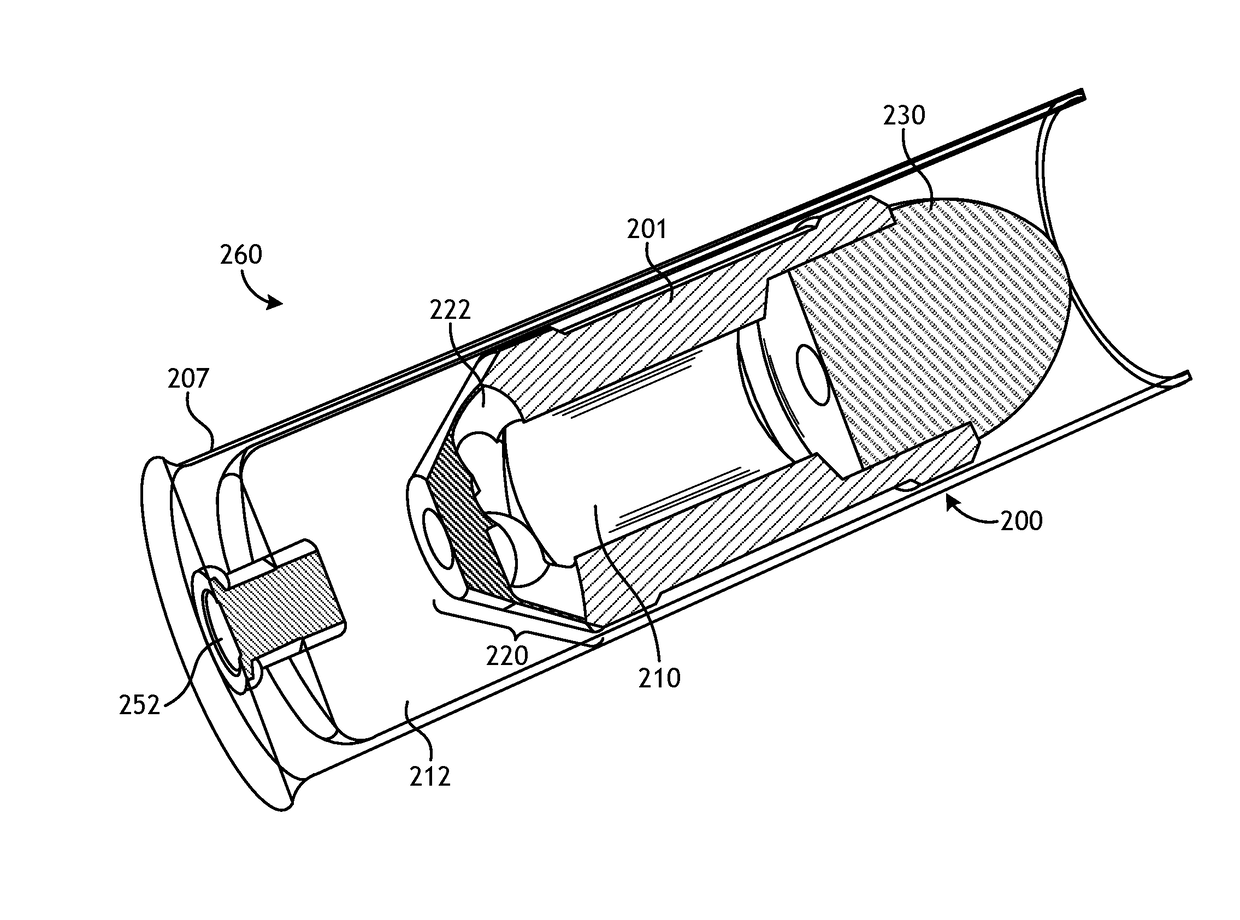
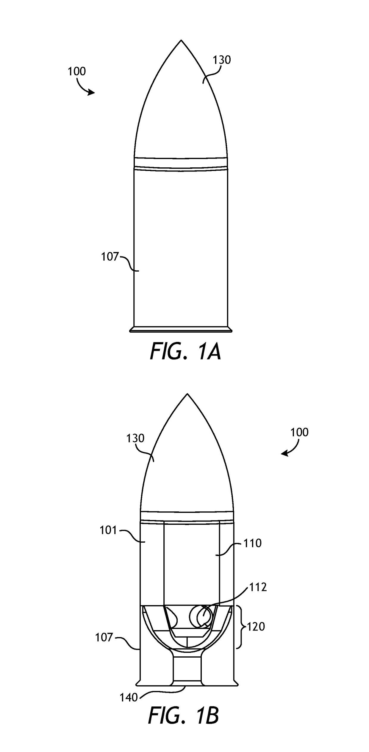
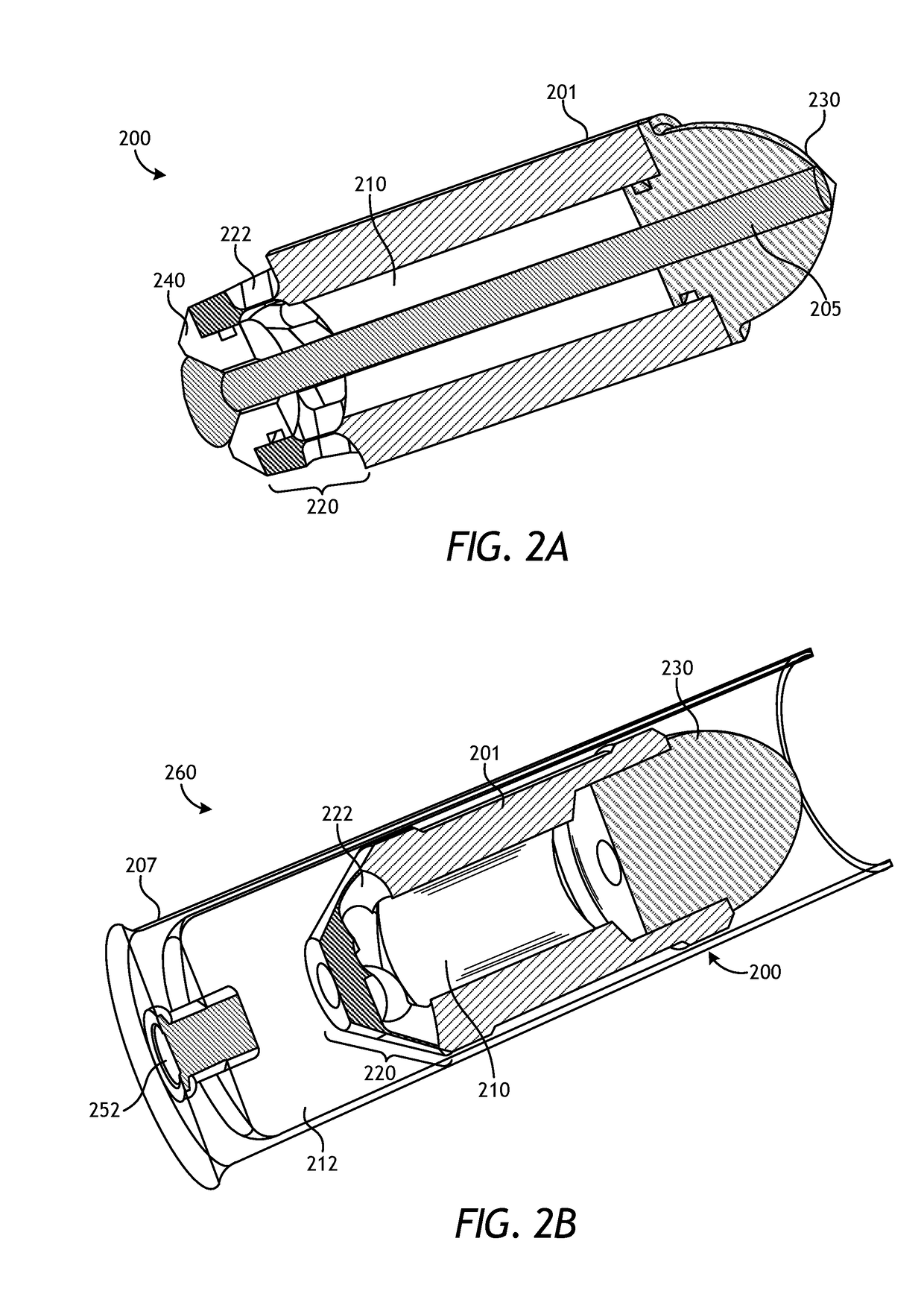
[0008]The present disclosure provides a projectile with a self-contained internal chamber. Reaction of propellant (such as by combustion or other mechanisms) inside the internal chamber can generate high pressure and the resultant exhaust gases can be used for projectile linear acceleration, rotational acceleration or other purposes. Torque can be produced by exhausting the pressure via radially placed, tangential nozzles or other outlets and can be configured to induce sufficient projectile spin to stabilize the projectile without the need for barrel rifling. The internal chamber may be separate or integral to the projectile itself. The projectile may include two or more chambers or compartments internal to the chambers. The disclosed projectile allows for higher pressures in the internal chamber than in the barrel and greater flexibility on pressure manipulation in the barrel and the projectile, allowing for a more efficient propellant combustion and manipulation of projectile characteristics such as muzzle and rotational speeds.

Problems solved by technology

The main disadvantage of placing the propellant behind the projectile is that the pressure trace (e.g., the barrel pressure as a function of time) is primarily governed by the propellant's reaction rate and is bell shaped, creating a pressure peak substantially higher than the average pressure experienced by the projectile while in the barrel.
The main disadvantage of rifling is the increased bullet / barrel friction.
Aggravated by cyclic thermal loading due to blow by gases squeezing their way through the engraving, the dry friction results in barrel contamination and surface deformation.
This leads to decreased accuracy after a few shots (without barrel cleaning) and ultimately results in barrel erosion, wear and the need for barrel replacement.
Modern, fast burning, high brisance propellants result in even shorter barrel life.
As propellant chemistry improves and cycle rates increase, thermal loading placed on rifling becomes excessive.
However, it is well known that plastic sabots also lead to barrel fouling.
Another disadvantage with using plastic sabots is that the round has to accelerate the mass of the plastic; however, such acceleration is parasitic, in terms of terminal ballistics, and only provides barrel protection services.
However, blow by reduces efficiency by wasting energy.
Moreover, incomplete, inefficient combustion and risk of complete extinction is present when sudden, random, drops in pressure occur due to the inherent unsteady leakage.
Moreover, placing the nozzles on the back of the projectile as is done in the Bunczk patent limits the radius at which the exhaust nozzles can be placed, provides limited angle, shape, and size of any exhaust nozzles, and greatly reduces the amount of mass flow / thrust from the internal chamber.
All of the above limits the amount of torque, and thus spin, that can be produced.
Simply put, existing ammunition provide numerous disadvantages, including projectile acceleration limited to short-pulse combustion methods with inefficient bell-shaped peak pressure trace patterns and mechanical rifling engagement that wears out after limited use.

Method used


Image

  • Self contained internal chamber for a projectile
  • Self contained internal chamber for a projectile
  • Self contained internal chamber for a projectile

Examples


Embodiment Construction

[0037]The Figures described above and the written description of specific structures and functions below are not presented to limit the scope of what Applicants have invented or the scope of the appended claims. Rather, the Figures and written description are provided to teach any person skilled in the art to make and use the inventions for which patent protection is sought. Those skilled in the art will appreciate that not all features of a commercial embodiment of the inventions are described or shown for the sake of clarity and understanding. Persons of skill in this art will also appreciate that the development of an actual commercial embodiment incorporating aspects of the present disclosure will require numerous implementation-specific decisions to achieve the developer's ultimate goal for the commercial embodiment. Such implementation-specific decisions may include, and likely are not limited to, compliance with system-related, business-related, government-related, and other ...


PUM


Abstract

The present disclosure provides a projectile with a self-contained internal chamber. Reaction of propellant inside the internal chamber can generate high pressure and the resultant exhaust gases can be used for projectile linear acceleration, rotational acceleration or other purposes. Torque can be produced by exhausting the pressure via radially placed, tangential nozzles or other outlets and can be configured to induce sufficient projectile spin to stabilize the projectile without the need for barrel rifling. The internal chamber may be separate or integral to the projectile itself. The projectile may include two or more chambers or compartments internal to the chambers. The disclosed projectile allows for higher pressures in the internal chamber than in the barrel and greater flexibility on pressure manipulation in the barrel and the projectile, allowing for a more efficient propellant combustion and manipulation of projectile characteristics such as muzzle and rotational speeds.

Description

PRIORITY[0001]This application claims priority to U.S. provisional patent application No. 62 / 330,989, filed on May 3, 2016, the entire content of which is incorporated herein by reference.BACKGROUND OF THE INVENTIONField of the Invention[0002]The disclosure generally relates to ammunition, e.g., bullets and other projectiles. Specifically, the disclosure relates to projectiles with an internal chamber that may serve as a high-pressure chamber used to improve performance characteristics of the projectile.Description of the Related Art[0003]A typical cartridge consists of a bullet (e.g., a projectile), a case or body that holds all the parts of the cartridge together, propellant (e.g., gunpowder) and a primer that ignites the propellant. A bullet or projectile is not a cartridge; rather, the bullet or projectile is just one component of the cartridge and is the part shot through the barrel of a firearm. The bullet may have a variety of shapes, such as spherical, conical, grooved, holl...

Claims


Application Information

Patent Timeline
Patent Type & Authority Applications(United States)
IPC IPC(8): F42B10/28F42B10/38F42B5/02
CPCF42B10/28F42B10/38F42B5/02F42B10/30F42B15/00F42B5/10
Inventor PANOUSAKIS, DIMOSTHENIS
Owner DIMOSTHENIS PANOUSAKIS
Why Eureka
Try Eureka