Method, apparatus and system for back gate biasing for fd-soi devices

Active Publication Date: 2017-11-09
GLOBALFOUNDRIES US INC
View PDF16 Cites 7 Cited by
  • Summary
  • Abstract
  • Description
  • Claims
  • Application Information

AI Technical Summary

Benefits of technology

The patent is about a semiconductor device with transistors that have back and front gates, and a signal processing unit that processes input signals to produce output signals. The device also includes a gain circuit and a bias circuit that provide signals to the back gates to control their operation. The technical effect of this invention is an improved semiconductor device that allows for better control and regulation of the transistors, leading to more efficient and accurate signal processing.

Problems solved by technology

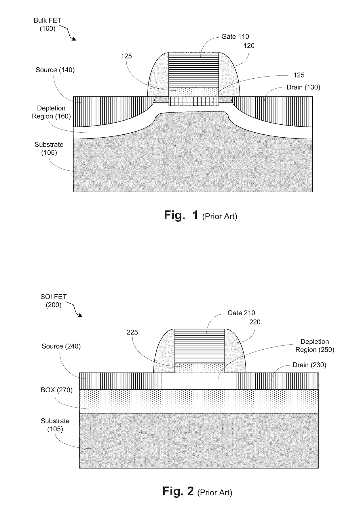
One of the problems associated with the typical bulk FET design of FIG. 1 includes the fact that these types of FETs can exhibit significantly reduced output resistance due to poor carrier confinement, leading to lower voltage gain and low power efficiency.
Moreover, when supply voltage is reduced in order to decrease power consumption, the typical bulk FET design of FIG. 1 tends to exhibit performance degradation.
One issue of concern with regard to FD-SOI devices is biasing issues in high-frequency applications.
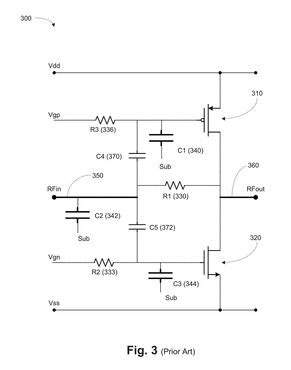
However, among the problems associated with the conventional design of the circuit 300 includes the fact this bias circuit designed to optimize gain and gain efficiency tends to increase signal path parasitic capacitance.
However, due to the existence of parasitic capacitances, portions of the current in the input signal RFin 350 may travel through the parasitic capacitances C1340, C2342, and C3344, which may result in undesirable power consumption and reduced signal bandwidth.
Further, the parasitic capacitances may cause performance degradation.
Also, the AC coupling capacitors tend to be large and use up valuable die real estate and increase production costs.

Method used


Image

  • Method, apparatus and system for back gate biasing for fd-soi devices
  • Method, apparatus and system for back gate biasing for fd-soi devices
  • Method, apparatus and system for back gate biasing for fd-soi devices

Examples


Embodiment Construction

[0033]Various illustrative embodiments of the invention are described below. In the interest of clarity, not all features of an actual implementation are described in this specification. It will of course be appreciated that in the development of any such actual embodiment, numerous implementation-specific decisions must be made to achieve the developers' specific goals, such as compliance with system-related and business-related constraints, which will vary from one implementation to another. Moreover, it will be appreciated that such a development effort might be complex and time-consuming, but would nevertheless be a routine undertaking for those of ordinary skill in the art having the benefit of this disclosure.

[0034]The present subject matter will now be described with reference to the attached figures. Various structures, systems and devices are schematically depicted in the drawings for purposes of explanation only and so as to not obscure the present disclosure with details ...


PUM


Abstract

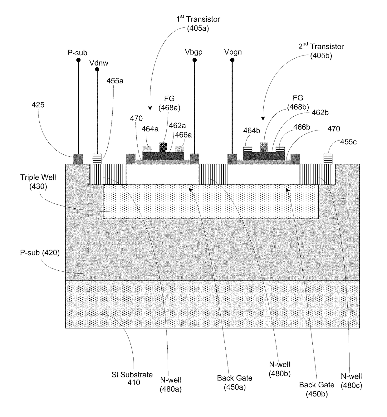
At least one method, apparatus and system disclosed involves providing semiconductor device having transistors comprising back gates and front gates. The semiconductor device comprises a signal processing unit for processing an input signal to provide an output signal. The signal processing unit includes a first transistor and a second transistor. The first transistor includes a first back gate electrically coupled to a first front gate. The signal processing unit also includes a second transistor operatively coupled to the first transistor. The second transistor includes a second back gate electrically coupled to a second front gate. The semiconductor device also includes a gain circuit for providing a gain upon the output signal. The semiconductor device also includes a bias circuit to provide a first bias signal to the first back gate and a second bias signal to the second back gate.

Description

FIELD OF THE INVENTION[0001]Generally, the present disclosure relates to the manufacture of sophisticated semiconductor devices, and, more specifically, to employing back gate biasing for a FD-SOI device.DESCRIPTION OF THE RELATED ART[0002]There is an ever-growing demand for integrated circuit devices (e.g., radio-frequency (RF) devices, system on chips that include digital and analog functionality, e.g., RF and / or other analog functionality, etc.) that provide more efficient operations. Therefore, designers are constantly attempting to improve semiconductor processing to manufacture better integrated circuit devices. The manufacture of semiconductor devices requires a number of discrete process steps to create a packaged semiconductor device from raw semiconductor material. The various processes, from the initial growth of the semiconductor material, the slicing of the semiconductor crystal into individual wafers, the fabrication stages (etching, doping, ion implanting, or the like...

Claims


Application Information

Patent Timeline
IPC IPC(8): H03F3/193H01L27/092H01L21/67H01L21/762H01L21/84H01L29/78H01L29/66H01L27/12G06F17/50H01L23/66H03G1/00H03F1/02H01L21/8238
CPCH03F3/193H01L21/823828H01L27/0928H03G1/0005H03F1/0205H01L21/7624H01L29/66484H01L29/7831H01L23/66H01L27/1203H01L21/67011G06F17/5045H03F2200/451H03F2200/267H01L21/823892H01L21/84H01L29/66575H01L29/7816G06F30/39H01L29/66772H01L29/78603H01L29/78648H01L29/78654H03F3/2173H03F3/3028H03F2200/456H03F2203/30031H03G1/0029G06F30/30
Inventor MCKAY, THOMAS G.
Owner GLOBALFOUNDRIES US INC
Why Eureka
Try Eureka