Gas-liquid separator

a gas-liquid separator and separator technology, applied in the direction of liquid fuel engines, separation processes, liquid degasification, etc., can solve the problems of increased replacement costs, clogging of the membrane, and the disadvantage of large space requirements, so as to achieve advanced gas-liquid separation, easy cleaning and reassembly, and easy expansion in size

Active Publication Date: 2017-11-16
YOKOTA SEISAKUSHO
View PDF1 Cites 9 Cited by
  • Summary
  • Abstract
  • Description
  • Claims
  • Application Information

AI Technical Summary

Benefits of technology

[0038]Because of this configuration, the apparatus according to the present invention performs advanced gas-liquid separation using a powerful vacuum device. It is free from troubles caused by pumped liquid penetration into the vacuum device, and is durable against an eccentric load to the rotating shaft caused by an uneven flow of the pumped liquid on the suction side. It can also be easily enlarged in size. Also, liquid contact parts can be cleaned without leaving any shadows during CIP cleaning, and easy disassembly cleaning and reassembly are also possible. Attachment and detachment of components for disassembly cleaning or inspection can be done with minimal labor. The system can be used with various kinds of liquids such as food materials and chemicals, and supports various specifications.

Problems solved by technology

Of the above systems, the heating and decompressing types are mainly for batch processing, and are unsuitable for continuous processing, and they have the further disadvantage of larger space requirements.
In the permeation membrane type system, clogging of the membrane occurs easily as a result of particles or solids in the liquid, and this entails increased replacement costs.
However, the following problems still remain unsolved.
Firstly, there remains the problem of insufficient gas-liquid separation performance when the system is applied to advanced defoaming or degassing operations.
In the centrifugation system, since the separation is performed using only the mass difference between the gas and liquid, if a powerful vacuum device is installed then the centrifugal separation performance may be overwhelmed by the suction power of the vacuum device, which may cause liquid penetration into the vacuum device.
Therefore, with the centrifugation system, it is no easy task to achieve powerful removal of the gas only.
This can become a constraint when applying the system to advanced defoaming or degassing operations, causing insufficient gas-liquid separation performance.
Secondly, in applications for treatment of food materials and ultra-pure liquids, there is the problem of insufficient cleanability, both for CIP (Cleaning In Place: internal cleaning without disassembly) cleaning and disassembly cleaning.
However, the structure of the centrifugation system is complicated due to its rotating parts, which means disassembly is difficult.
CIP cleaning of liquid contact parts without leaving any shadows is also difficult due to the complicated passages.
In Original Invention 1, however, the aforementioned second problem, that is the insufficient cleanability of the system, has not been resolved in any way.
There is, instead, the occurrence of new shadows or bottlenecks which create cleaning problems such as on the back side of the cavity holder 35 or in the exhaust pipe 36 installation part.
The system cannot be used with various kinds of liquids because there is the possibility of clogging due to the bottleneck in the case of liquids such as food materials that contain particles or lumps.
Further problems also occur.
For example, because the cavity is simply drawn into the exhaust pipe 36 opening, if the formed cavity becomes unstable, then the entry of pumped liquid into the exhaust passage cannot be prevented.
Therefore it is extremely practical and useful, however the following problems still remain unsolved in some applications, particularly when increasing its size.
Firstly, it is vulnerable to an eccentric load to the rotating shaft 3 in the radial direction caused when the flow of the pumped liquid flowing in from the suction inlet a becomes uneven.
In particular when the liquid is highly viscous or contains lumps, this eccentric load may further increase and result in axial runout, posing a problem for a smooth operation of this apparatus.
Secondly, it still requires improvement in terms of workability in disassembly or assembly operations.
However, if the apparatus is enlarged, there are problems in the disassembly cleaning and reassembly operations.
Attachment and detachment of the longish, bulky and heavy casing 1a under the large overhang condition is not easy, and attachment and detachment of piping at the suction inlet a or the discharge outlet b of the casing 1a is also troublesome.

Method used


Image

  • Gas-liquid separator
  • Gas-liquid separator
  • Gas-liquid separator

Examples


embodiment 1

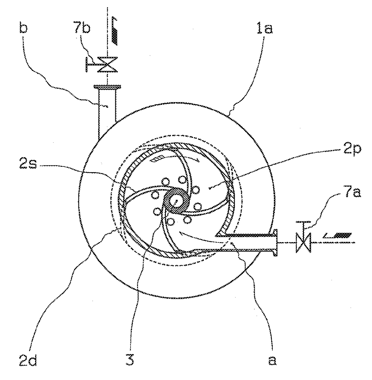
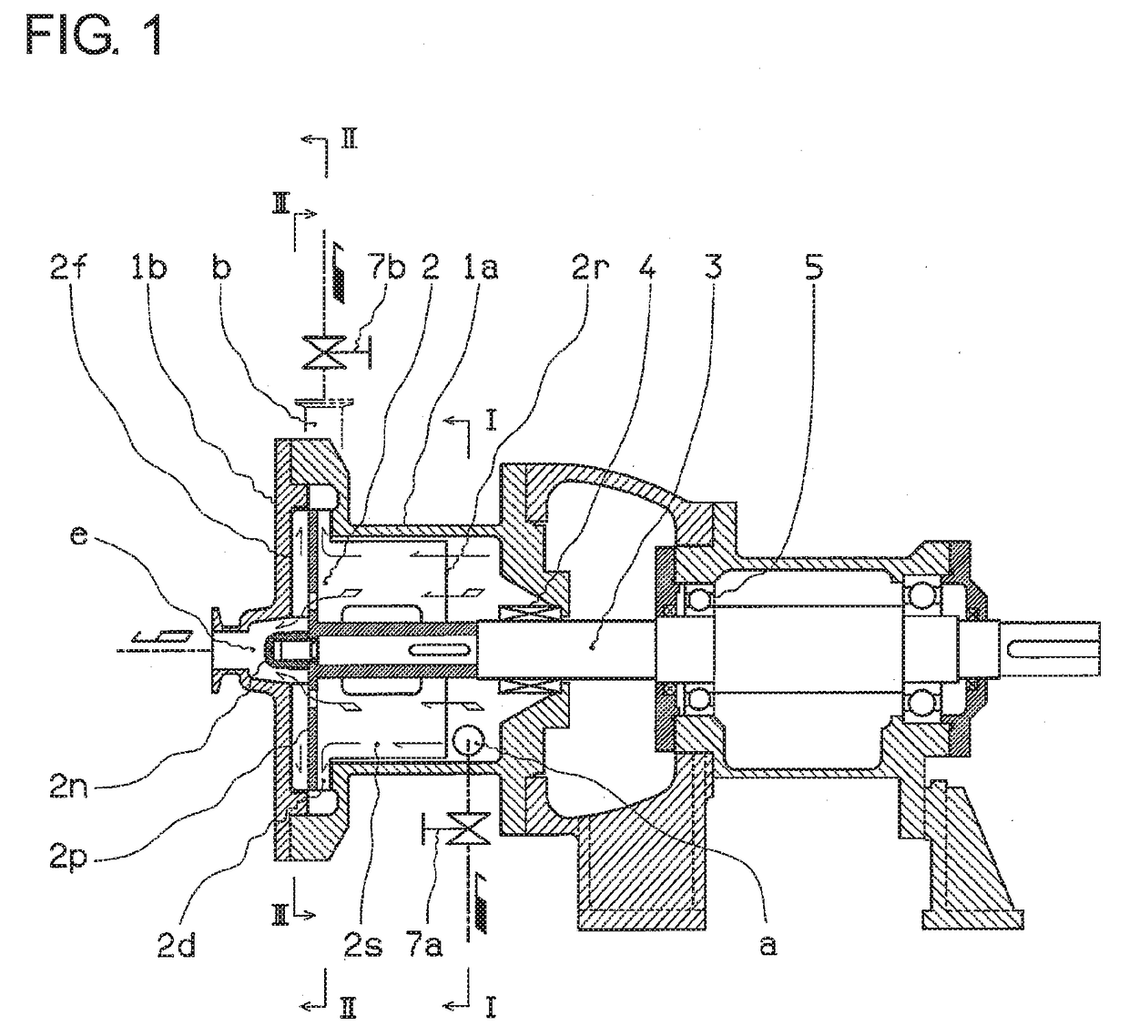
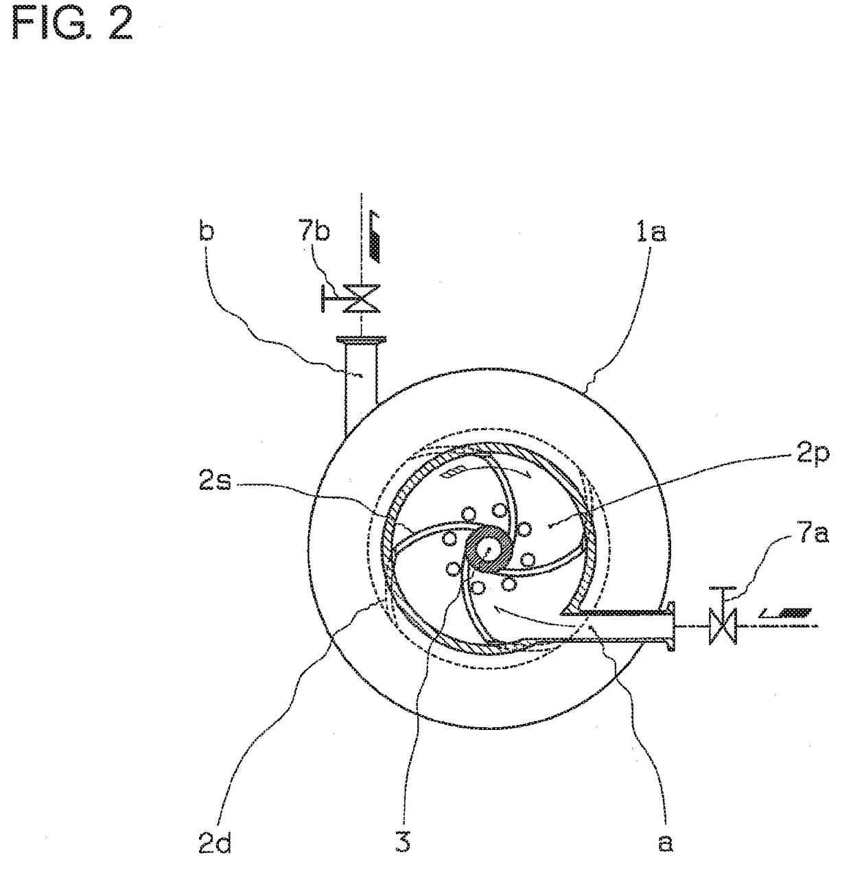
[0066]FIG. 1 shows the first embodiment of the present invention, FIG. 2 shows section I-I in FIG. 1, FIG. 3 shows section II-II in FIG. 1, and FIG. 4 shows section III-III in FIG. 1.

[0067]A casing can be separated into 1a and 1b and forms one cylindrical chamber when connected, and an impeller 2 with a suitable number of vanes is disposed in the casing 1a and 1b. The impeller 2, with an outer diameter that allows for a small clearance with respect to the inner peripheral wall of the casing 1a, is mounted to one end of a rotating shaft 3. Although it may be mounted by screwing, it is here mounted with an impeller nut 2n as illustrated in this embodiment. The rotating shaft 3 is supported by a shaft bearing part 5, and penetrates the casing 1a with tight sealing at a shaft sealing part 4. A motor, not shown in the figure, drives the rotation.

[0068]The impeller 2 is provided with a separation impeller part 2s which performs gas-liquid separation in all areas around the rotating periph...

embodiment 2

[0089]FIG. 5 shows the second embodiment, and FIG. 6 shows section I-I in FIG. 5.

[0090]In this embodiment, the opening for the suction inlet a to the inside of the casing 1a is disposed in a position inwardly apart from the inner peripheral wall of the casing 1a by a predetermined distance so as to improve degassing efficiency.

[0091]One of the important factors in improving the degassing efficiency of a gas-liquid separator is increasing the gas-liquid boundary area (the surface area where liquid is exposed to the negative pressure generated by the vacuum device). For this purpose, specific methods include enlarging the diameter of the annular boundary surface by throttling the inflow to reduce the radial thickness of the annular liquid layer generated by the centrifugal separation, or enlarging the casing 1a itself either in the radial direction or in the axial direction. However, the former method creates a problematic trade-off relationship with the maximum processable flow rate,...

embodiment 3

[0099]FIG. 7 shows the third embodiment, and FIG. 8 shows section I-I in FIG. 7.

[0100]In this embodiment, the suction inlet a in the apparatus of the second embodiment is modified such that its opening is formed in a straight nozzle or spray nozzle shape. This shape enables the pumped liquid to be dispersed in the cavity area more easily, further increasing the gas-liquid boundary area and improving the degassing efficiency.

[0101]This nozzle or spray can also function as a throttle for the pumped liquid.

[0102]As shown in the figure, the baffle member 2q can be suitably provided with small vanes to enhance centrifugal separation of the pumped liquid.

[0103]The rest of the constitution and functions are the same as those of the second embodiment.


PUM

PropertyMeasurementUnit
centrifugal forceaaaaaaaaaa
discharge forceaaaaaaaaaa
distanceaaaaaaaaaa

Abstract

The present invention provides a gas-liquid separator with enhanced performance and easy operation, capable of performing gas-liquid separation such as advanced defoaming or degassing, and with a structure that facilitates easy CIP cleaning and disassembly cleaning, allowing it to meet sanitary specifications.This gas-liquid separator for gas-liquid separation performed by centrifugal force of an impeller mounted on a shaft which is supported by a bearing part and rotates in a casing comprises: the axial end of the impeller farther from the bearing part being positioned with clearance from the inner wall of the casing so as to slide on the inner wall of the casing; an exhaust outlet of the casing disposed in a position opposite the sliding impeller part; a vacuum device connected to the exhaust outlet; a discharge impeller part providing discharge force to the passing fluid formed around the axial end of the impeller; a discharge outlet of the casing disposed in a position opposite the discharge impeller part; and a suction inlet of the casing disposed in a position closer to the bearing part than the discharge outlet.

Description

TECHNICAL FIELD[0001]The present invention relates to a gas-liquid separator that performs advanced gas-liquid separation such as defoaming or degassing, and is easy to clean and disassemble, and is suitable for sanitary specifications.BACKGROUND ART[0002]Generally recognized systems referred to as gas-liquid separators for defoaming and degassing include container type devices that are filled with liquid and then heated or decompressed, systems that employ a gas permeation membrane which only the gas can pass, and systems employing centrifugation.[0003]Of the above systems, the heating and decompressing types are mainly for batch processing, and are unsuitable for continuous processing, and they have the further disadvantage of larger space requirements. In the permeation membrane type system, clogging of the membrane occurs easily as a result of particles or solids in the liquid, and this entails increased replacement costs.[0004]In contrast, the centrifugation system is suitable ...

Claims


Application Information

Patent Timeline
Patent Type & Authority Applications(United States)
IPC IPC(8): B01D45/14B01D19/00A47L9/16
CPCB01D45/14B01D19/0057A47L9/1675A47L7/0014B01D19/0052B01D19/00F04B53/06B01D19/0042
Inventor KAWAMOTO, ISAOKUMANAKA, SHINJITAKAHASHI, KENJI
Owner YOKOTA SEISAKUSHO
Why Eureka
Try Eureka