Underwater positioning system

a positioning system and underwater technology, applied in vehicle positioning/course/altitude control, process and machine control, instruments, etc., can solve the problems of devices being sensitive to subsea noise and image processing being more complex, and achieve greater redundancy and fault tolerance, less data, and enhanced resulting calculations

Active Publication Date: 2017-11-16
FUGRO
View PDF0 Cites 22 Cited by
  • Summary
  • Abstract
  • Description
  • Claims
  • Application Information

AI Technical Summary

Benefits of technology

[0077]The light sources may be placed at positions in or on the rover that enhance the resulting calculations and at distances dependent upon the visibility. In one embodiment, at least three light sources should be visible from any single location but more preferably, four or more light sources may be visible in order to provide greater redundancy and fault tolerance.
[0078]The method preferably comprises determining the direction data by viewing the light sources with the imaging device, determining the co-ordinates of the center of a light source and transmitting the co-ordinates to a processing device without the transmission of further image data. As has been described above, the imaging device may be adapted to only identify the centers of given light sources in order to determine the angle subtended at the reference plane of the imaging device. Processing can therefore take place on the basis of this data alone and other surrounding imagery need not be transmitted by the beaco

Problems solved by technology

Additionally, illumination of the object or marker leads to backscattering of light making image processing more complex.
Nevertheless, a

Method used


Image

  • Underwater positioning system
  • Underwater positioning system
  • Underwater positioning system

Examples


first embodiment

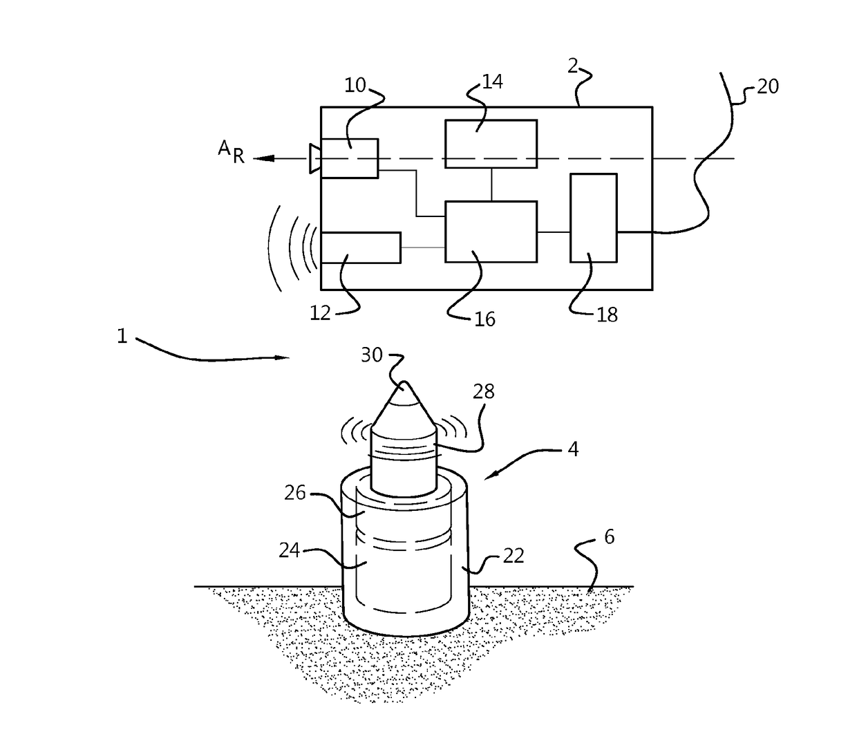
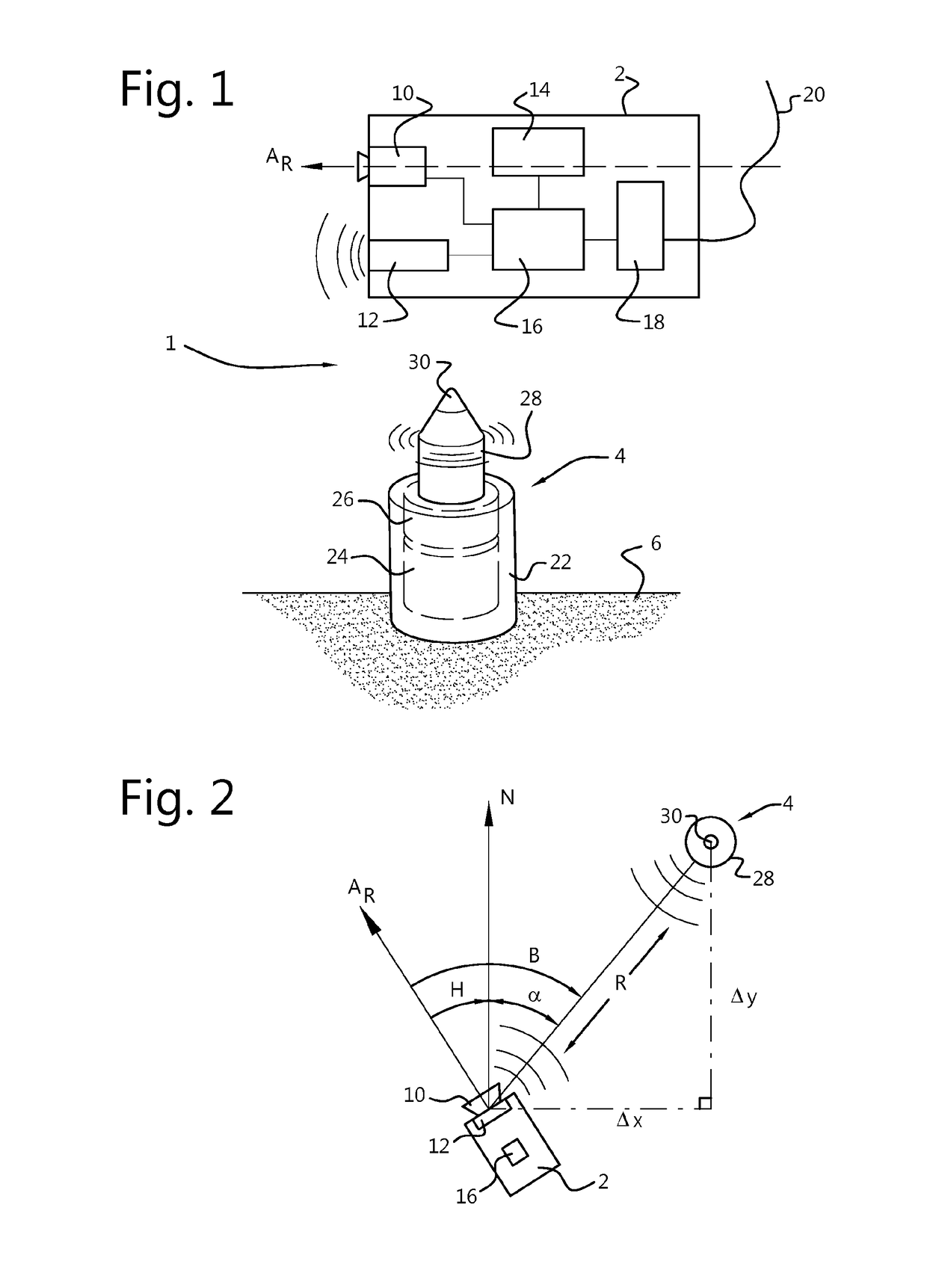
[0101]FIG. 1 shows a schematic view of an underwater positioning system 1 according to a The system comprises an ROV 2 and a beacon 4, both being suitable for underwater operation, the beacon being located on the seabed 6. The ROV 2 includes a photogrammetric camera 10, an acoustic transceiver 12, an orientation sensor 14, processor 16 and a communications interface 18, which connects with an umbilical 20. The ROV 2 may be a generally conventional device as used for underwater operations and survey and will be further provided with all of the necessary facilities for maneuvering itself and other objects and for communicating with the surface. It will also be understood that although the embodiments are explained with reference to an ROV, the same principles may be applied to completely autonomous vehicles and to handheld rovers carried by a diver or the like. The camera 10 is a calibrated wide-angle camera having a field of view of around 120 degrees and directed to produce an imag...

second embodiment

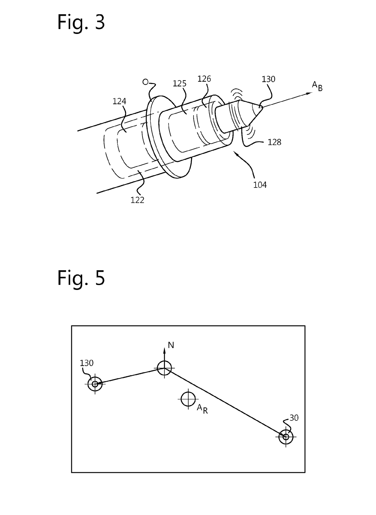
[0108]FIG. 6 shows part of a positioning system 101 according to the invention. The system 101 includes an ROV 102 with additional capabilities and is shown in operation to survey a first underwater object O1. The ROV 102 is similar to that of FIG. 1 and like features are designated with similar reference numerals preceded by 100. According to FIG. 6, the ROV 102 has first and second cameras 110, 111, located a distance apart and both directed forwards, allowing stereoscopic vision. Furthermore, the ROV 102 is provided with an INS 113, a depth gauge 115 and a laser line scanner 117 allowing 3-D perception of objects within image range. Also shown in FIG. 6 is a passive beacon 204 located on the seabed 6 close to the object O1. The passive beacon 204 is similar to beacon 2 of FIG. 1 but comprises only a light source 230 and battery 224, without acoustic transponder or further electronics or communication capability. For the sake of clarity, the beacons 4 and 104 having communication ...

third embodiment

[0111]FIG. 8 depicts a beacon 304 according to a Beacon 304 includes three light sources 330a, b, c located at three corners of a triangular frame 331 mounted on a base 322, including a transponder 328. The frame is isosceles in shape with the light sources 330b and 330c being closer together and light source 330A being relatively distant. The distances between the light sources 330a-c are carefully defined and can be used by an ROV to determine both scale and the direction in which the beacon 304 is pointed i.e. the location of light source 330a. It will be understood that the light sources 330a-c may also differ in color or be arranged to flash in different sequences should additional identification be required.


PUM


Abstract

An underwater positioning system provides position information for a rover, moveable within a reference frame. The system may comprise: at least one beacon having a light source, located at a fixed position within the reference frame; an underwater imaging device, moveable with the rover in the reference frame to observe the light source from different viewpoints and determine direction data representing a direction or change in direction of the light source with respect to the imaging device; an orientation sensor, associated with the imaging device to determine an orientation of the imaging device with respect to the reference frame and generate orientation data; and a scaling element for providing scaling data representative of a distance between the imaging device and the light source. Various different beacons may be provided.
In alternative system implementations, the locations of light source(s) and underwater imaging device are reversed between rover and beacon(s).

Description

TECHNICAL FIELD[0001]The present invention relates to systems and methods for positioning in an underwater environment and more particularly to a system of beacons for such use. The invention also relates to a subsea metrology system for determining the relative positions and orientations of two objects.BACKGROUND ART[0002]During subsea operations, it is frequently necessary to accurately identify the position and or orientation of an object, either in absolute terms or relative to another object. Such objects may include oil pipelines and flanges, engineering structures, geological structures, salvage items and the like. Presently, much of the work in this context takes place using remotely operated vehicles (ROVs). Nevertheless, it will be understood that similar issues apply in the case of human divers, manned submarine devices and unmanned Autonomous Underwater Vehicles (AUV's) and the invention is equally applicable to all underwater rovers.[0003]In general, for a rover, precis...

Claims


Application Information

Patent Timeline
IPC IPC(8): G01S5/16B63C7/26G01S1/70G05D1/06
CPCG01S5/16B63C7/26G05D1/0692G01S1/70G01S2201/07
Inventor JONGSMA, ARNOUD MARCSONNIER, CARL
Owner FUGRO
Why Eureka
Try Eureka