Alkali vapor cell

a technology of alkali vapor cells and vapor cells, which is applied in the direction of pre-selected time interval producing apparatus, automatic control of pulses, instruments, etc., can solve the problems of high reactivity of alkali metals with oxygen and water, light shift effect, and drastic reduction of fabrication costs, so as to achieve the effect of higher alkali metal wettability

Active Publication Date: 2017-11-16
CSEM CENT SUISSE DELECTRONIQUE & DE MICROTECHNIQUE SA RECH & DEV
View PDF3 Cites 38 Cited by
  • Summary
  • Abstract
  • Description
  • Claims
  • Application Information

AI Technical Summary

Problems solved by technology

On the other hand a major challenge is related to the high reactivity of these alkali metals with oxygen and water.
Advantage of MEMS fabrication techniques is that thanks to the small size of the vapor cells hundreds or even thousands of vapor cells can be fabricated at once on a single silicon wafer, which cuts drastically the fabrication costs.
One of the issues arising from such very small volume vapor cells is that the size of a cross-section of the cavity in a plane perpendicular to the optical beam is close to the diameter of the optical beam itself, usually a laser beam, used to interrogate optically the alkali vapor cell by spectral absorption.
While this phenomenon is generally unwanted, a much more critical problem arises if the size, the shape or the location of the non-transparent areas within the light path is modified during the operation of the cell.
Such uncontrolled variations lead to light shift effect.
In a miniaturized vapor cell of a few cubic millimeters or smaller, precise localization of the metallic alkali outside the optical beam path is not easily realized in this way.
Creating a thermal gradient allowing a well-defined localization within distances of 100 micrometers implies a complex set-up and a slow process which is not easily achievable at a wafer scale level and it will increase fabrication costs considerably.
Furthermore, during storage, when the cell temperature experiences an uncontrolled temperature gradient, the alkali metal can migrate to an unwanted location by the same mechanism.
The thermal insulation of the heated vapor cell must be nearly perfect and any cold spot would be the source of an inacceptable power loss.
Thus, a problem caused by a thermal gradient during storage might result in a permanently dysfunctional device.

Method used


Image

  • Alkali vapor cell
  • Alkali vapor cell
  • Alkali vapor cell

Examples


implementation example

Detailed Implementation Example

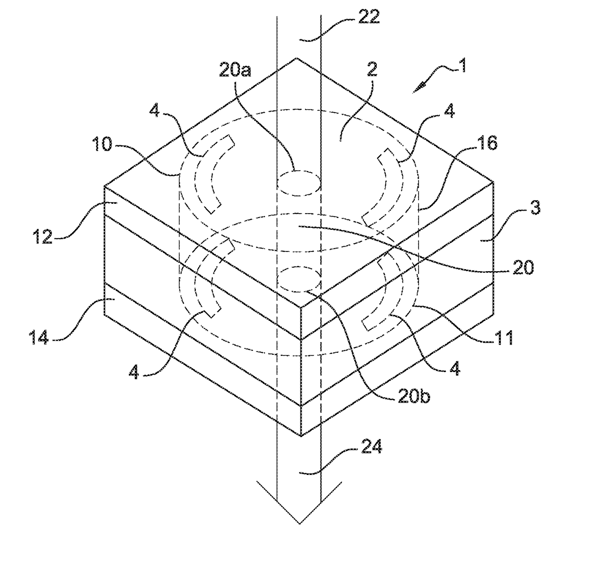
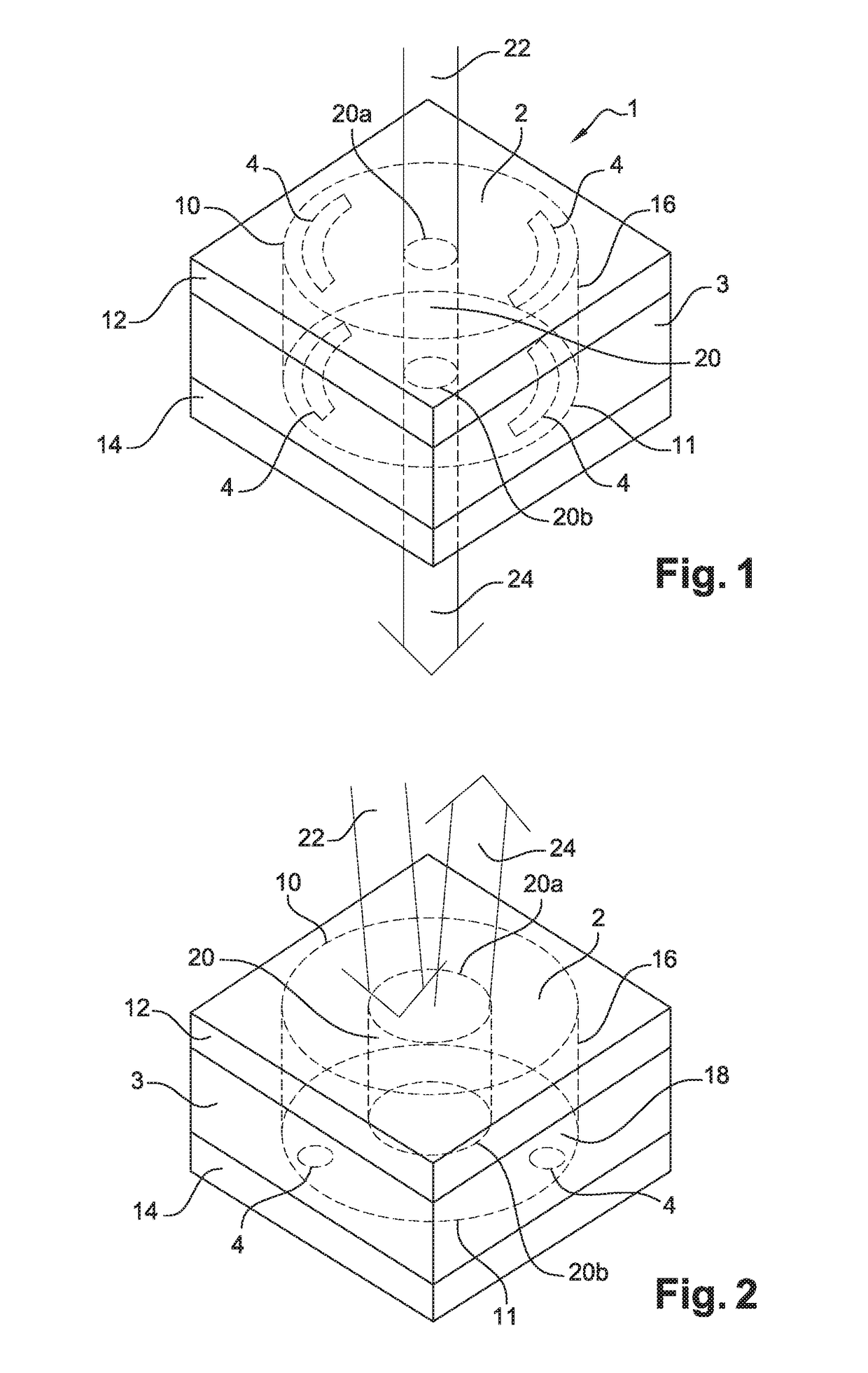
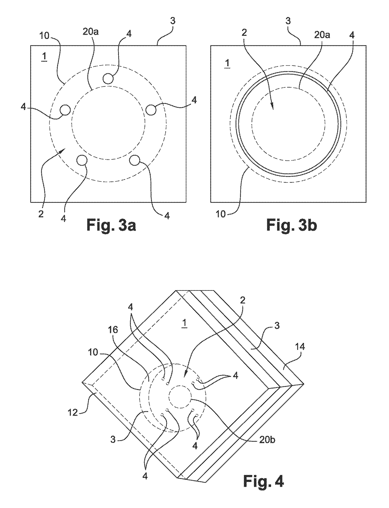
[0100]Alkali vapor cells 1 according to the invention are fabricated by etching through holes of 2 mm diameter into a 1 mm thick silicon wafer followed by anodic bonding of a first borofloat glass wafer of 0.2 mm thickness onto one side of the silicon wafer. Following this process step, the cavities 2 are filled with 10 nL of aqueous RbN3 solution of 100 g / L concentration using a dispenser from Microdrop Technologies GmbH, type MD-K-130-030. The details of deposition of dissolved RbN3 solution are disclosed in patent application US 20120301631 (A1). On a second borofloat glass wafer of 0.2 mm thickness, discs of 80 μm diameter with 10 nm Ti adhesion layer followed by 50 nm Au are structured by lift-off process. The open cavities in the silicon wafer are then hermetically closed by anodic bonding using the second glass wafer, with the gold discs being exposed to the cavities. The configuration of the gold discs is such that eight gold discs are exposed ...


PUM


Abstract

In the present invention an alkali vapor cell is proposed comprising a sealed chamber enclosing an alkali atomic gas therein and having at least one optically transparent window. The chamber and the transparent window define an optical beam path through which a light beam can pass and which interacts with the alkali atomic gas in the chamber. The alkali vapor cell comprises at least one localized condensation area of alkali atoms at a predetermined location in the sealed chamber and the predetermined location is located inside or outside the optical beam path. The localized condensation area has higher alkali metal wettability than any other surface portion of the alkali vapor cell outside said localized condensation area.

Description

TECHNICAL FIELD[0001]The present invention relates to the field of frequency reference and spectroscopic devices. More particularly, the present invention relates to alkali vapor cells of miniaturized atomic clocks having a reduced size and that may be integrated in portable systems.BACKGROUND OF THE INVENTION[0002]Atomic clocks have been developed since more than 50 years, following fundamental scientific progress and developments in the field of quantum mechanics and microwave spectroscopy. Atomic clocks are based on microwave emission as a result of electronic transitions between the electronic energy levels of atoms. In practice alkali metals, in particular rubidium (Rb) and cesium (Cs), are the preferred choice for the interrogation due to their relative simple electron configuration and their high vapor pressure at relatively low temperatures. On the other hand a major challenge is related to the high reactivity of these alkali metals with oxygen and water. For this purpose th...

Claims


Application Information

Patent Timeline
Patent Type & Authority Applications(United States)
IPC IPC(8): H03L7/26G04F5/14
CPCH03L7/26G04F5/14G04F5/145G01R33/26
Inventor GOBET, JEANOVERSTOLZ, THOMASDROZ-DIT-BUSSET, FABIEN
Owner CSEM CENT SUISSE DELECTRONIQUE & DE MICROTECHNIQUE SA RECH & DEV
Why Eureka
Try Eureka