
Porous electrode substrate, membrane-electrode assembly using same, and polymer electrolyte fuel cell using same

a technology of electrolyte fuel cell and porous electrode, which is applied in the direction of cell components, final product manufacturing, sustainable manufacturing/processing, etc., can solve the problems of sheet tending to warp, no significant improvement in dewatering capability, and neither is sufficient to achieve mechanical strength and dewatering capability

Active Publication Date: 2017-11-23
MITSUBISHI CHEM CORP
View PDF2 Cites 5 Cited by
  • Summary
  • Abstract
  • Description
  • Claims
  • Application Information

AI Technical Summary

Benefits of technology

This patent describes a porous electrode substrate that can be used in a variety of fuel cell conditions. This includes low-temperature and wet conditions as well as high-temperature and dry conditions. The patent also provides a membrane-electrode assembly and a polymer electrolyte fuel cell that utilizes this porous electrode substrate. The technical effect of this invention is the ability to create a versatile and adaptable electrode substrate that can be used in a wide range of fuel cell conditions.

Problems solved by technology

Accordingly, efficient discharge of water produced by reactions is the issue, and high dewatering capability is thereby required for carbonized sheets used as gas diffusion materials in fuel cells.
However, neither is sufficient to achieve both mechanical strength and dewatering capability.
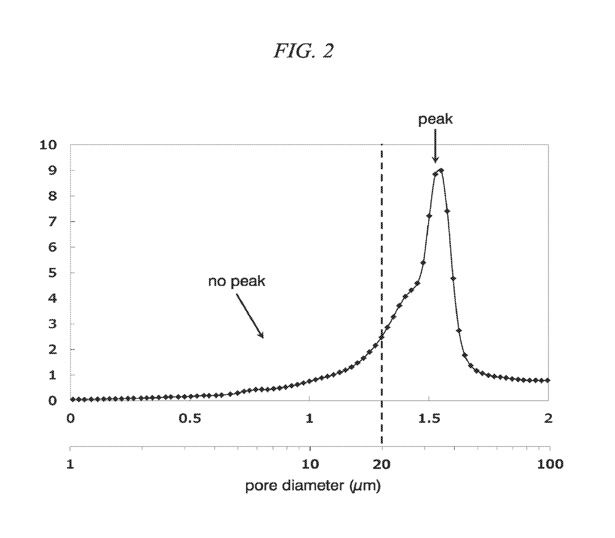
However, only a peak of those with a pore diameter of no larger than 1 μm is observed in the pore distribution, and thus no significant improvement in dewatering capability is achieved.
However, the sheet tends to warp due to different upper- and lower-side structures.
In addition, those literatures do not clearly indicate how to set pore distributions for improving dewatering capability and enhancing fuel cell performance.
Accordingly, the method is not suitable for automotive applications.
However, no description is provided for controlling pore distributions in such a process.
The problem factor leading to a decrease in cell performance is insufficient gas supply caused by a clog in the substrate or separator passages, also known as flooding or plugging, that may instantaneously decrease power generation capability in a relatively low-temperature high-current-density region.
Accordingly, when a route is clogged by the produced water, gas diffusion is blocked, and drying accelerates once it starts, thereby resulting in a dry-up phenomenon.

Method used


Image

  • Porous electrode substrate, membrane-electrode assembly using same, and polymer electrolyte fuel cell using same
  • Porous electrode substrate, membrane-electrode assembly using same, and polymer electrolyte fuel cell using same
  • Porous electrode substrate, membrane-electrode assembly using same, and polymer electrolyte fuel cell using same

Examples


example 1

[0150]Prepared materials: polyacrylonitrile (PAN)-based carbon fibers (product name: Pyrofil TR50S, average fiber diameter: 7 μm, made by Mitsubishi Rayon Co., Ltd.) cut to have an average fiber length of 3 mm, polyvinyl alcohol (PVA) fibers (product name: VPB105-1, fiber length: 3 mm, made by Kuraray Co., Ltd), and polyethylene pulp (product name: SWP, made by Mitsui Chemicals Inc.). PAN-based carbon fibers, polyethylene pulp and PVA fibers at a ratio of 10:3:2 were charged into the slurry tank of a continuous wet papermaking machine with a short wire mesh, water was further added to the tank and the fibers were evenly dispersed and opened. When the fibers were fully dispersed, the web was discharged, passed onto the short wire mesh, and dried with a blower. Accordingly, a rolled carbon-fiber sheet material was obtained to have a width of 1000 mm and a basis weight of 20 g / m2.

[0151]Next, the carbon-fiber sheet material was immersed in a methanol solution with a phenolic resin (prod...

examples [UNK]

Examples 2˜6

[0155]Compositions of carbon-fiber sheet materials in Examples 2˜6 were all the same as that in Example 1. However, in Examples 4˜6, the basis weight of the carbon-fiber sheet material was changed to 40 g / m2, and the number of laminations in the double-belt pressing process was changed from two to one. As shown in Table 1, conditions of temperatures and the pressure of pressing rolls were changed respectively for sampling. Carbonization conditions were the same as those in Example 1.

example 7

[0156]Prepared materials: PAN-based carbon fibers with an average fiber diameter of 7 μm and an average fiber length of 3 mm, acrylic fibers with an average fiber diameter of 4 μm and an average fiber length of 3 mm (product name: D122, made by Mitsubishi Rayon), and polyethylene pulp (product name: SWP, made by Mitsui Chemicals). A sheet material and a three-dimensionally entangled sheet were respectively produced by a continuous wet papermaking method and by entanglement treatment through continuous high-pressure water jetting as described below.

[0157]

(1) Defibration of Carbon Fibers (A)

[0158]PAN-based carbon fibers with an average fiber diameter of 7 μm and an average fiber length of 3 mm were dispersed in water to have a fiber concentration of 1% (10 g / L) and were defibrated through a disc refiner (made by Kumagai Riki Kogyo Co., Ltd.) to make defibrated fiber slurry (SA).

(2) Defibration of Carbon Fiber Precursors (b 1)

[0159]Acrylic fibers with an average fiber diameter of 4 μm ...


PUM

PropertyMeasurementUnit
lengthaaaaaaaaaa
diameteraaaaaaaaaa
pore diameteraaaaaaaaaa

Abstract

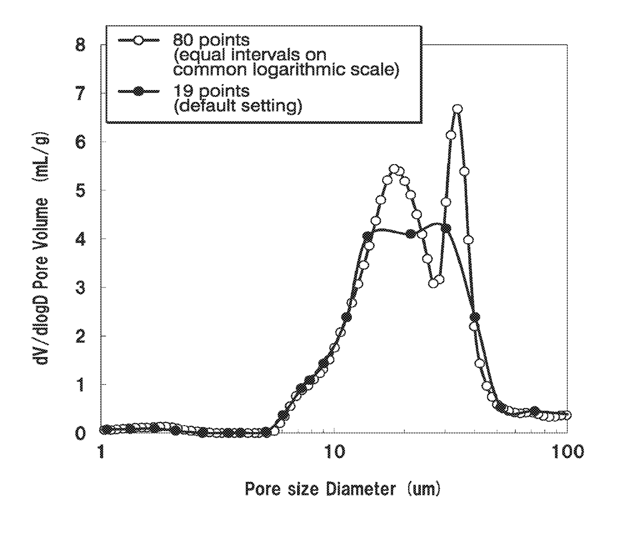
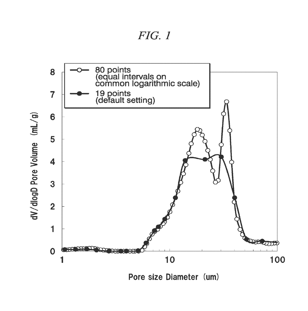
Disclosed herein is a porous electrode substrate in which carbon fibers are dispersed in the structure thereof have a fiber diameter of 3-15 micron and a fiber length of 2-30 mm, and are bound to one another by carbonized resin such that, when a pore distribution in the porous electrode is determined with a mercury intrusion porosimeter, such that a pore distribution curve is plotted on a graph having a common logarithmic scale on the horizontal axis, and a 1-100 micron pore diameter range of the pore distribution curve includes 80 or more measurement points at equal intervals along the common logarithmic scale, the pore distribution has a skewness S of -2.0<S<-0.8 and a kurtosis K of 3.5<K<10 in the 1-100 micron pore diameter range.

Description

TECHNICAL FIELD[0001]The present invention relates to a porous electrode substrate applied for a polymer electrolyte fuel cell, a membrane-electrode assembly comprising the porous electrode substrate, and a polymer electrolyte fuel cell comprising the membrane-electrode assembly.[0002]The present application is based upon and claims the benefit of priority to Japanese Application Nos. 2014-223950, filed Nov. 4, 2014, and 2015-196501, filed Oct. 2, 2015, the entire contents of which are incorporated herein by reference.BACKGROUND ART[0003]Polymer electrolyte fuel cells are required to have high conductivity and excellent current collection capability while exhibiting mechanical strength to withstand various operations. Also, the diffusion of substances that contribute to electrode reactions needs to be excellent in such fuel cells. To respond to such requirements, carbonized sheets are generally used as electrode substrates. Fuel cell applications that have attracted attention in rec...

Claims


Application Information

Patent Timeline
Patent Type & Authority Applications(United States)
IPC IPC(8): H01M4/92H01M4/86H01M8/1018
CPCH01M4/926H01M8/1018H01M4/8668B32B5/02H01M8/0234H01M8/0239H01M8/0245H01M2008/1095H01M4/8605H01M4/96H01M8/1004Y02E60/50Y02P70/50
Inventor TATSUNO, HIROTONAKAMURA, MAKOTO
Owner MITSUBISHI CHEM CORP
Learn More